
Please click " Note for Discontinuation and Replacement models " for the details.
* Note for discontinuation of Encoder Types: Incremental encoder, Absolute encoder (RCS2-RA5, RCS2-RGD5, RCS2-RGS5, RCS2-SA7, RCS2-SM, RCS2-SS, RCS2-SS7, RCS2-SS8, RCS2CR-SA7, RCS2CR-SM, RCS2CR-SS, RCS2CR-SS7, RCS2CR-SS8, RCS3-SA8, RCS3-SS8, RCS3CR-SA8, RCS3CR-SS8, RCS3P-SA8, RCS3P-SS8, RCS3PCR-SA8, RCS3PCR-SS8)
Available Encoder Type Now: Battery-less Absolute Encoder
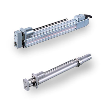
RCS2-RGS4C / 5C Single Guide Rod Type
Coupling 200V Servo Electric Actuator
|


RCS2-RGS4C Rod Type with Single Guide,
Actuator Diameter Q37mm, 200V Servo Motor, Coupling Specification
RCS2-RGS5C Rod Type with Single Guide,
Actuator Width 55mm, 200V Servo Motor, Coupling Specification
|
|

|
RCS2-RGS4C Electric Actuator Lead and Load Capacity
|
Model
|
Motor Output (W) |
Lead (mm)
|
Maximum load capacity*
|
Rated Thrust (N) |
Stroke (mm)
|
| Horizontal (kg) |
Vertical (kg) |
| RCS2-RGS4C-[1]-20-12-[2]-[3]-[4]-[5] |
20
|
12
|
3.0
|
0.5
|
18.9
|
50-300
|
| RCS2-RGS4C-[1]-20-6-[2]-[3]-[4]-[5] |
6
|
6.0
|
1.5
|
37.7
|
| RCS2-RGS4C-[1]-20-3-[2]-[3]-[4]-[5] |
3
|
12.0
|
3.5
|
75.4
|
| RCS2-RGS4C-[1]-30-12-[2]-[3]-[4]-[5] |
30
|
12
|
4.0
|
1.0
|
28.3
|
| RCS2-RGS4C-[1]-30-6-[2]-[3]-[4]-[5] |
6
|
9.0
|
2.5
|
56.6
|
| RCS2-RGS4C-[1]-30-3-[2]-[3]-[4]-[5] |
3
|
18.0
|
6.0
|
113.1
|
[1] = Encoder Type, [2] = Stroke, [3] = Applicable Controller, [4] = Cable Length, [5] = Options
RCS2-RGS4C Stroke and Maximum Speed
|
Lead
|
Stroke
|
50-300 mm
|
|
12
|
600
|
|
6
|
300
|
|
3
|
150
|
(Unit: mm/s)
RCS2-RGS4C Specs
|
Item
|
Description
|
|
Drive Method
|
Ball screw Θ10mm, rolled C10
|
|
Positioning Repeatability
|
±0.02mm
|
|
Backlash
|
0.05mm or less
|
|
Guide
|
Single guide, guide rod diameter Θ10mm, ball bush type
|
|
Rod Diameter
|
Θ20mm
|
|
Rod Non-Rotation Accuracy
|
±0.05°
|
|
Ambient Operating Temp/Humidity
|
0-40 °C, 85% RH or below (non-condensing)
|
|
RCS2-RGS4C Options
| Name |
Model |
Page |
|
Home Sensor
|
NJ
|
|
|
Foot Bracket
|
FT
|
|
Reversed-Home Specification
|
NM
|
|
Rear Trunnion
|
TRR
|
|
Brake
|
B
|
|
 |
(1) When the stroke increases, the maximum speed will drop to prevent the ball screw from reaching a critical speed. Use the actuator specification table above to check the maximum speed at the stroke you desire.
(2) The load capacity is based on operation at an acceleration of 0.3G (or 0.2G if the lead is 3 or the actuator is operated vertically). This is the maximum acceleration.
(3) The horizontal load capacity assumes used of an external guide and absence of external force applied from any direction other than the moving direction of the rod. |
|
RCS2-RGS4C Controllers
RCS2 series actuators can be operated using the following controllers.
Choose the type that best suits your specific purpose.
|
Name
|
Model
|
Features
|
Max Positioning Points
|
Input Power Supply
|
Power Supply Capacity
|
Reference
|
|
Positioner Type
|
SCON-C-20[1]-NP-2-[2]
SCON-C-30D[1]-NP-2-[2]
|
Supports up to 512 positioning points
|
512 points
|
Single Phase 100VAC
Single Phase 200VAC
Three Phase 200VAC
|
360VA max.
*1-axis specification, operated at 150W
|
|
|
Solenoid Valve Mode
|
Same control actions as those applicable to solenoid valves
|
3 points
|
|
Serial Communication Type
|
Dedicated serial communication type
|
64 points
|
|
Pulse-train Input Control Type
|
Dedicated pulse-train input type
|
(-)
|
|
Program Control, 1 or 2-Axis Type
|
SSEL-C-1-20[1]-NP-2-[2]
SSEL-C-1-30D[1]-NP-2-[2]
|
Programmable type capable of operating up to 2 axes
|
1500 points
|
|
Program Control, 1 to 6-Axis Type
|
XSEL-[3]-1-20[1]-N1-EEE-2-[2]
XSEL-[3]-1-30D[1]-N1-EEE-2-[2]
|
Programmable type capable of operating up to 6 axes
|
4000 points
|
*The SSEL and XSEL model names are based on a 1-axis specification.
*[1] indicates the encoder type (I: Incremental / A: Absolute).
*[2] indicates the power-supply voltage type (1: 100V / 2: Single-phase 200V / 3: Three-phase 200V).
*[3] indicates the XSEL type (J/K/P/Q).
|
RCS2-RGS5C Electric Actuator Lead and Load Capacity
|
Model
|
Motor Output (W) |
Lead (mm)
|
Maximum load capacity*
|
Rated Thrust (N) |
Stroke (mm)
|
| Horizontal (kg) |
Vertical (kg) |
| RCS2-RGS5C-[1]-60-16-[2]-[3]-[4]-[5] |
60
|
16
|
12.0
|
1.3
|
63.8
|
50-300
|
| RCS2-RGS5C-[1]-60-8-[2]-[3]-[4]-[5] |
8
|
25.0
|
4.3
|
127.5
|
| RCS2-RGS5C-[1]-60-4-[2]-[3]-[4]-[5] |
4
|
50.0
|
10.8
|
255.1
|
| RCS2-RGS5C-[1]-100-16-[2]-[3]-[4]-[5] |
100
|
16
|
15.0
|
2.8
|
105.8
|
| RCS2-RGS5C-[1]-100-8-[2]-[3]-[4]-[5] |
8
|
30.0
|
8.3
|
212.7
|
| RCS2-RGS5C-[1]-100-4-[2]-[3]-[4]-[5] |
4
|
60.0
|
17.3
|
424.3
|
[1] = Encoder Type, [2] = Stroke, [3] = Applicable Controller, [4] = Cable Length, [5] = Options
RCS2-RGS5C Stroke and Maximum Speed
|
Lead
|
Stroke
|
50~250mm |
300 mm
|
|
16
|
800
|
755
|
|
8
|
400
|
377
|
|
4
|
200
|
188
|
(Unit: mm/s)
RCS2-RGS5C Specs
|
Item
|
Description
|
|
Drive Method
|
Ball screw Θ12mm, rolled C10
|
|
Positioning Repeatability
|
±0.02mm
|
|
Backlash
|
0.05mm or less
|
|
Guide
|
Single guide, guide rod diameter Θ12mm, ball bush type
|
|
Rod Diameter
|
Θ20mm
|
|
Rod Non-Rotation Accuracy
|
±0.1°
|
|
Ambient Operating Temp/Humidity
|
0-40 °C, 85% RH or below (non-condensing)
|
|
RCS2-RGS5C Options
| Name |
Model |
Page |
|
Cable Outlet Direction
|
A2
|
|
|
Brake
|
B
|
|
Foot Bracket
|
FT
|
|
Guide Installation Direction Change
|
GS2-GS4
|
|
|
(1) When the stroke increases, the maximum speed will drop to prevent the ball screw from reaching a critical speed. Use the actuator specification table above to check the maximum speed at the stroke you desire.
(2) The load capacity is based on operation at an acceleration of 0.3G (or 0.2G if the lead is 3 or the actuator is operated vertically). This is the maximum acceleration.
(3) The horizontal load capacity assumes used of an external guide and absence of external force applied from any direction other than the moving direction of the rod. |
|
RCS2-RGS5C Controllers
RCS2 series actuators can be operated using the following controllers.
Choose the type that best suits your specific purpose.
|
Name
|
Model
|
Features
|
Max Positioning Points
|
Input Power Supply
|
Power Supply Capacity
|
Reference
|
|
Positioner Type
|
SCON-C-60[1]-NP-2-[2]
SCON-C-100[1]-NP-2-[2]
|
Supports up to 512 positioning points
|
512 points
|
Single Phase 100VAC
Single Phase 200VAC
Three Phase 200VAC
|
360VA max.
*1-axis specification, operated at 150W
|
|
|
Solenoid Valve Mode
|
Same control actions as those applicable to solenoid valves
|
3 points
|
|
Serial Communication Type
|
Dedicated serial communication type
|
64 points
|
|
Pulse-train Input Control Type
|
Dedicated pulse-train input type
|
(-)
|
|
Program Control, 1 or 2-Axis Type
|
SSEL-C-1-60[1]-NP-2-[2]
SSEL-C-1-100[1]-NP-2-[2]
|
Programmable type capable of operating up to 2 axes
|
1500 points
|
|
Program Control, 1 to 6-Axis Type
|
XSEL-[3]-1-60[1]-N1-EEE-2-[2]
XSEL-[3]-1-100[1]-N1-EEE-2-[2]
|
Programmable type capable of operating up to 6 axes
|
4000 points
|
*The SSEL and XSEL model names are based on a 1-axis specification.
*[1] indicates the encoder type (I: Incremental / A: Absolute).
*[2] indicates the power-supply voltage type (1: 100V / 2: Single-phase 200V / 3: Three-phase 200V).
*[3] indicates the XSEL type (J/K/P/Q).
|
Please refer to ROBO Cylinder General Catalog
Do you have any questions or comments about our products? Contact Us
Go to:
 |