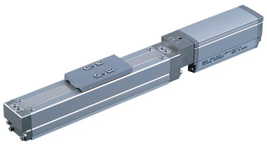
__________
Go to Part Search page to quick search another product PDF.
__________
 |
|
Speed vs. Load Capacity
Due to the characteristics of the pulse motor, the RCP3 series' load capacity decreases at high speeds.
In the table below, check if your desired speed and load capacity are supported.

Lead and Load Capacity
| Model | Lead (mm) |
Max. Load Capacity | Maximum Push Force (N) |
Stroke (mm) |
|
| Horizontal (kg) |
Vertical (kg) |
||||
| RCP3-SA3C-I-28P-6-[1]-[2]-[3]-[4] | 6 | 1 | 0.5 | 15 | 50~300 (50mm increments) |
| RCP3-SA3C-I-28P-4-[1]-[2]-[3]-[4] | 4 | 2 | 1 | 22 | |
| RCP3-SA3C-I-28P-2-[1]-[2]-[3]-[4] | 2 | 3 | 1.5 | 44 | |
Legend: [1] = Stroke, [2] = Compatible Controller, [3] = Cable Length, [4] = Options
Stroke and Maximum Speed
| Stroke | 50 ~ 300 (50mm increments) |
| Lead | |
| 6 | 300 |
| 4 | 200 |
| 2 | 100 |
(Unit: mm/s)
Actuator Specifications
| Item | Description |
| Drive System | Ball screw Ø6mm C10 grade |
| Positioning Repeatability | ±0.02mm |
| Lost Motion | 0.1mm or less |
| Base | Material: Aluminum (special alumite treated) |
| Allowable Static Moment | Ma: 5.0N∙m Mb: 7.1N∙m Mc: 7.9 N∙m |
| Allowable Dynamic Moment(*) | Ma: 1.96N∙m Mb: 2.84N∙m Mc: 3.14N∙m |
| Overhang Load Length | 100mm or less |
| Ambient Operating Temp./Humidity | 0~40°C, 85% RH or less (non-condensing) |
(*) Based on 5,000km travel life.

[1] Stroke List
| Stroke (mm) |
| 50 |
| 100 |
| 150 |
| 200 |
| 250 |
| 300 |
[2] Compatible Controllers
The RCP3 series actuators can operate with the controllers below. Select the controller according to your usage.
| Name | External View |
Model | Description | Max. Positioning Points |
Input Voltage |
Power Supply Capacity |
See Page |
| Solenoid Valve Type |
PMEC-C-28PI-NP-2-{1} | Easy-to-use controller, even for beginners | 3 points | AC100V AC200V |
See P.481 | P.477 | |
| PSEP-C-28PI-NP-2-0 | Operable with same signal as solenoid valve. Supports both single and double solenoid types. No homing necessary with simple absolute type. | DC24V | 2A Max. | P.487 | |||
| Splash-Proof Solenoid Valve Type |
PSEP-CW-28PI-NP-2-0 | ||||||
| Positioner Type |
PCON-C-28PI-NP-2-0 | Positioning is possible for up to 512 points | 512 points | P.525 | |||
| Safety-Compliant Positioner Type |
PCON-CG-28PI-NP-2-0 | ||||||
| Pulse Train Input Type (Differential Line Driver) |
PCON-PL-28PI-NP-2-0 | Pulse train input type with differential line driver support | (−) | ||||
| Pulse Train Input Type (Open Collector) |
PCON-PO-28PI-NP-2-0 | Pulse train input type with open collector support | |||||
| Serial Communication Type |
PCON-SE-28PI-N-0-0 | Dedicated to serial communication | 64 points | ||||
| Field Network Type |
RPCON-28P | Dedicated to field network | 768 points | P.503 | |||
| Program Control Type |
PSEL-C-1-28PI-NP-2-0 | Programmed operation is possible. Can operate up to 2 axes | 1500 points | P.557 |
* This is for the single-axis PSEL.
* {1} is a placeholder for the power supply voltage (1: 100V / 2: 100~240V).
[3] Cable List
| Type | Cable Symbol |
| Standard (Robot Cables) |
P (1m) |
| S (3m) | |
| M (5m) | |
| Special Lengths | X06 (6m) ~ X10 (10m) |
| X11 (11m) ~ X15 (15m) | |
| X16 (16m) ~ X20 (20m) |
* The standard cable is the motor-encoder integrated robot cable..
* See page A-39 for connection cable models.
[4] Option List
| Name | Option Code | See Page |
| Brake-Equipped | B | A-25 |
| Cable Exit Direction (Top) | CJT | A-25 |
| Cable Exit Direction (Right) | CJR | A-25 |
| Cable Exit Direction (Left) | CJL | A-25 |
| Cable Exit Direction (Bottom) | CJB | A-25 |
| No Cover | NCO | A-33 |
| Reversed-home | NM | A-33 |
This product is in the ROBO Cylinder General Catalog.
Do you have any questions or comments about our products? Contact Us.


