|


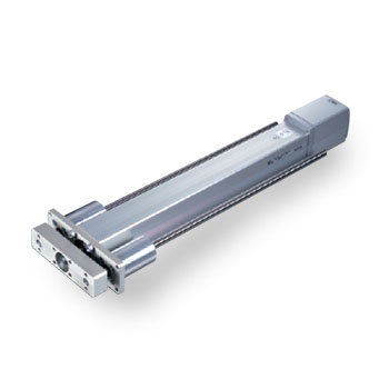
RCP2-RGD3C Double Guide Rod Type, Actuator Width 35mm, Pulse Motor, Straight
RCP2-RGD4C Double Guide Rod Type, Actuator Width 45mm, Pulse Motor, Straight
RCP2-RGD6C Double Guide Rod Type, Actuator Width 64mm, Pulse Motor, Straight
|
|

|
RCP2-RGD3C Electric Actuator Lead and Load Capacity
|
Model
|
Lead (mm)
|
Maximum load capacity*
|
Max Push Force (N) (#) |
Stroke (mm)
|
| Horizontal (kg) |
Vertical (kg) |
| RCP2-RGD3C-I-28P-5-[1]-P1-[2]-[3] |
5
|
~15.0
|
~5
|
73.5
|
50~200
|
| RCP2-RGD3C-I-28P-2.5-[1]-P1-[2]-[3] |
2.5
|
~30.0
|
~9.0
|
156.8
|
[1] = Stroke, [2] = Cable Length, [3] = Options
*Take note that the maximum load capacity will decrease as the speed increases.
#Refer to RCP2-RGD3C pdf
RCP2-RGD3C Stroke and Maximum Speed
|
Lead
|
Stroke
|
50~200mm |
|
5
|
187
|
|
2.5
|
144<93>
|
(Unit: mm/s)
RCP2-RGD3C Specs
|
Item
|
Description
|
|
Drive Method
|
Ball Screw Θ8mm, rolled C10
|
|
Positioning Repeatability
|
±0.02mm
|
|
Backlash
|
0.05mm or less
|
|
Guide
|
Single guide, guide rod diameter Θ10mm, ball bush type
|
|
Rod Diameter
|
Θ22mm
|
|
Rod Non-Rotation Accuracy
|
±0.05°
|
|
Ambient Operating Temp/Humidity
|
0-40 °C, 85% RH or below (non-condensing)
|
|
RCP2-RGD3C Options
| Name |
Model |
Page |
|
Reversed-home Specification
|
NM
|
|
|
Foot Bracket
|
FT
|
|
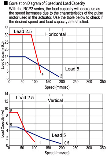
RCP2-RGD3C Correlation Diagram of Speed and Load Capacity
 |
(1) When the stroke increases, the maximum speed will drop to prevent the ball screw from reaching a critical speed. Use the actuator specification table below to check the maximum speed at the stroke you desire.
(2) With the RCP2 series, the load capacity will decrease as the speed increases due to the characteristics of the pulse motor used in the actuator. Use the correlation diagram of speed and load capacity on the right to check the load capacity at the speed you desire.
(3) The load capacity is based on operation at an acceleration of 0.2G. This is the maximum acceleration. The horizontal load capacity assumes use of an external guide. The horizontal load capacity assumes use of an external guide. Refer to Technical Reference for the weight that can be supported with the supplied guide alone. |
|
RCP2-RGD3C Controllers
RCP2 series actuators can be operated using the following controllers.
Choose the type that best suits your specific purpose.
|
Name
|
Model
|
Features
|
Max Positioning Points
|
Input Power Supply
|
Power Supply Capacity
|
Reference
|
|
Positioner Type
|
PCON-C-28PI-NP-2-0
|
Supports up to 512 positioning points
|
512 points
|
DC24V
|
2A max.
|
|
|
Positioner type meeting safety category
|
PCON-CG-28PI-NP-2-0
|
|
Solenoid Valve Type
|
PCON-CY-28PI-NP-2-0
|
Same control actions as those applicable to solenoid valves
|
3 points
|
|
Pulse-train Input Type (differential line driver specification)
|
PCON-PL-28PI-NP-2-0
|
Pulse-train input type supporting a differential line driver
|
(-)
|
|
Pulse-train Input Type (open collector specification)
|
PCON-PO-28PI-NP-2-0
|
Pulse-train input type supporting an open collector
|
|
Serial Communication Type
|
PCON-SE-28PI-0-0
|
Dedicated serial communication type
|
64 points
|
|
Program Control Type
|
PSEL-C-1-28PI-NP-2-0
|
Programmable type capable of operating up to 2 axes
|
1500 points
|
|
RCP2-RGD4C Electric Actuator Lead and Load Capacity
|
Model
|
Lead (mm)
|
Maximum load capacity*
|
Max Push Force (N) (#) |
Stroke (mm)
|
| Horizontal (kg) |
Vertical (kg) |
| RCP2-RGD4C-I-42P-10-[1]-P1-[2]-[3] |
10
|
~25.0
|
~3.5
|
150
|
50-300
|
| RCP2-RGD4C-I-42P-5-[1]-P1-[2]-[3] |
5
|
~40.0
|
~11.0
|
284
|
| RCP2-RGD4C-I-42P-2.5-[1]-P1-[2]-[3] |
2.5
|
40.0
|
~18.0
|
358
|
[1] = Stroke, [2] = Cable Length, [3] = Options
*Take note that the maximum load capacity will decrease as the speed increases.
RCP2-RGD4C Stroke and Maximum Speed
|
Lead
|
Stroke
|
50-200mm |
250mm |
300mm
|
|
10
|
458
|
458
|
350
|
|
5
|
250
|
237
|
175
|
|
2.5
|
125 <114>
|
118<114>
|
87
|
*The figures in <> apply when the actuator is used vertically. (Unit: mm/s)
RCP2-RGD4C Specs
|
Item
|
Description
|
|
Drive Method
|
Ball Screw Θ8mm, rolled C10
|
|
Positioning Repeatability
|
±0.02mm
|
|
Backlash
|
0.05mm or less
|
|
Rod Diameter
|
Θ22mm
|
|
Rod Non-Rotation Accuracy
|
±0.05°
|
|
Ambient Operating Temp/Humidity
|
0-40 °C, 85% RH or below (non-condensing)
|
|
RCP2-RGD4C Options
| Name |
Model |
Page |
|
Flange
|
FL
|
|
|
Foot Bracket
|
FT
|
|
Reversed-Home Specification
|
NM
|
|
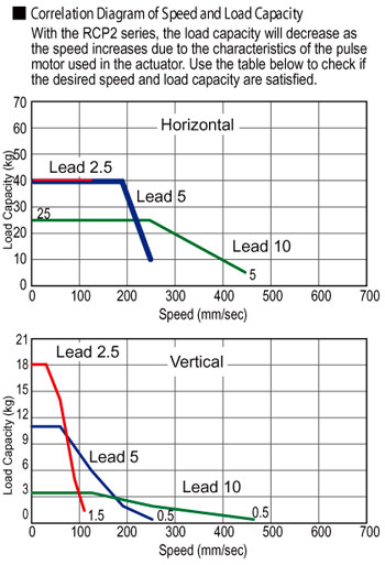
RCP2-RGD4C Correlation Diagram of Speed and Load Capacity
|
(1) When the stroke increases, the maximum speed will drop to prevent the ball screw from reaching a critical speed. Use the actuator specification table below to check the maximum speed at the stroke you desire.
(2) With the RCP2 series, the load capacity will decrease as the speed increases due to the characteristics of the pulse motor used in the actuator. Use the correlation diagram of speed and load capacity on the right to check the load capacity at the speed you desire.
(3) The load capacity is based on operation at an acceleration of 0.2G. This is the maximum acceleration. The horizontal load capacity assumes use of an external guide. The horizontal load capacity assumes use of an external guide. Refer to Technical Reference for the weight that can be supported with the supplied guide alone. |
|
RCP2-RGD4C Controllers
RCP2 series actuators can be operated using the following controllers.
Choose the type that best suits your specific purpose.
|
Name
|
Model
|
Features
|
Max Positioning Points
|
Input Power Supply
|
Power Supply Capacity
|
Reference
|
|
Positioner Type
|
PCON-C-42PI-NP-2-0
|
Supports up to 512 positioning points
|
512 points
|
DC24V
|
2A max.
|
|
|
Positioner type meeting safety category
|
PCON-CG-42PI-NP-2-0
|
|
Solenoid Valve Type
|
PCON-CY-42PI-NP-2-0
|
Same control actions as those applicable to solenoid valves
|
3 points
|
|
Pulse-train Input Type (differential line driver specification)
|
PCON-PL-42PI-NP-2-0
|
Pulse-train input type supporting a differential line driver
|
(-)
|
|
Pulse-train Input Type (open collector specification)
|
PCON-PO-42PI-NP-2-0
|
Pulse-train input type supporting an open collector
|
|
Serial Communication Type
|
PCON-SE-42PI-0-0
|
Dedicated serial communication type
|
64 points
|
|
Program Control Type
|
PSEL-C-1-42PI-NP-2-0
|
Programmable type capable of operating up to 2 axes
|
1500 points
|
|
RCP2-RGD6C Electric Actuator Lead and Load Capacity
|
Model
|
Lead (mm)
|
Maximum load capacity*
|
Max Push Force (N) (#) |
Stroke (mm)
|
| Horizontal (kg) |
Vertical (kg) |
| RCP2-RGD6C-I-56P-16-[1]-P1-[2]-[3] |
16
|
~40.0
|
~5.0
|
240
|
50-200
|
| RCP2-RGD6C-I-56P-8-[1]-P1-[2]-[3] |
8
|
~50.0
|
~17.5
|
470
|
| RCP2-RGD6C-I-56P-4-[1]-P1-[2]-[3] |
4
|
~55.0
|
~26.0
|
800
|
[1] = Stroke, [2] = Cable Length, [3] = Options
*Take note that the maximum load capacity will decrease as the speed increases.
RCP2-RGD6C Stroke and Maximum Speed
|
Lead
|
Stroke
|
50-300mm
|
|
5
|
450 <400>
|
|
2.5
|
210
|
|
4
|
130
|
*The figures in <> apply when the actuator is used vertically. (Unit: mm/s)
RCP2-RGD6C Specs
|
Item
|
Description
|
|
Drive Method
|
Ball Screw Θ12mm, rolled C10
|
|
Positioning Repeatability
|
±0.02mm
|
|
Backlash
|
0.05mm or less
|
|
Rod Diameter
|
Θ2mm
|
|
Rod Non-Rotation Accuracy
|
±0.05°
|
|
Ambient Operating Temp/Humidity
|
0-40 °C, 85% RH or below (non-condensing)
|
|
RCP2-RGD6C Options
| Name |
Model |
Page |
|
Flange
|
FL
|
|
|
Foot Bracket
|
FT
|
|
Reversed-Home Specification
|
NM
|
|
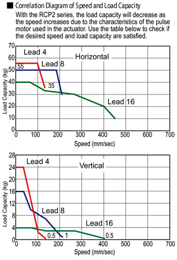
RCP2-RGD6C Correlation Diagram of Speed and Load Capacity
|
(1) When the stroke increases, the maximum speed will drop to prevent the ball screw from reaching a critical speed. Use the actuator specification table below to check the maximum speed at the stroke you desire.
(2) With the RCP2 series, the load capacity will decrease as the speed increases due to the characteristics of the pulse motor used in the actuator. Use the correlation diagram of speed and load capacity on the right to check the load capacity at the speed you desire.
(3) The load capacity is based on operation at an acceleration of 0.2G. This is the maximum acceleration. The horizontal load capacity assumes use of an external guide. The horizontal load capacity assumes use of an external guide. Refer to Technical Reference for the weight that can be supported with the supplied guide alone. |
|
RCP2-RGD6C Controllers
RCP2 series actuators can be operated using the following controllers.
Choose the type that best suits your specific purpose.
|
Name
|
Model
|
Features
|
Max Positioning Points
|
Input Power Supply
|
Power Supply Capacity
|
Reference
|
|
Positioner Type
|
PCON-C-56PI-NP-2-0
|
Supports up to 512 positioning points
|
512 points
|
DC24V
|
2A max.
|
|
|
Positioner type meeting safety category
|
PCON-CG-56PI-NP-2-0
|
|
Solenoid Valve Type
|
PCON-CY-56PI-NP-2-0
|
Same control actions as those applicable to solenoid valves
|
3 points
|
|
Pulse-train Input Type (differential line driver specification)
|
PCON-PL-56PI-NP-2-0
|
Pulse-train input type supporting a differential line driver
|
(-)
|
|
Pulse-train Input Type (open collector specification)
|
PCON-PO-56PI-NP-2-0
|
Pulse-train input type supporting an open collector
|
|
Serial Communication Type
|
PCON-SE-56PI-0-0
|
Dedicated serial communication type
|
64 points
|
|
Program Control Type
|
PSEL-C-1-56PI-NP-2-0
|
Programmable type capable of operating up to 2 axes
|
1500 points
|
|
Please refer to ROBO Cylinder General Catalog
Do you have any questions or comments about our products? Contact Us
Go to:
 |