Please click " Discontinuation Notice and Replacement Models " for the details.
* Notice for the discontinuation and replacement models of PS-24 DC Power Supply (PS-241 and PS-242).
PSA-24 / PSA-24L - 24VDC Power Supply latest Models
Please click Replacement Model: PSA-24 and PSA-24L for the details.
![]()
- Maximum Momentary Output of 17A -
Up to 17A of maximum momentary output current is possible at 8.5A rated output current.
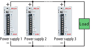
- Parallel Operation Enabled -
Up to 5 unites can be operated in parallel.
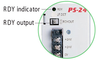
- Load Detection Function -
Load percentage can be detected by the RDY (Ready) display lamp.
| Features | |||||||||||||||||||||||||||||||||||||||||||||||||||||||||||||
Maximum Momentary Output of 17AWhile the rated output current is 8.5A, maximum momentary output current of up to 17A is supported. This lets you select an appropriate power-supply capacity based on the total rated current of actuators, without having to consider the maximum momentary current that may be generated by the actuator during acceleration.
Because you no longer need to use an expensive high-capacity power supply, cost can be reduced substantially. * The maximum momentary output current must be considered if the actuator operating conditions are tight. For details, refer to "Selection Guide" on the right.
Supporting Parallel Operation
Load Detection Function
Selection Guide: Number of Actuators ConnectedWhen selecting a power-supply unit for operating multiple actuators, normally a unit with a capacity equal to or exceeding the total maximum current of all actuators is chosen. However, actuators generate their maximum current only momentarily during acceleration, etc., and in many cases the power-supply is over-specified. On the other hand, the PS-24 power supply provides the following advantages:
Number of Power-supply UnitsBasically, how many power-supply units you need should be determined in such a way that the total rated current of all actuators will remain within the rated current of the PS-24.
Examples of Tight Load Condition
Table 1. Rated Current of PS-24 and Allowable Maximum Momentary Current
(Note) Consider a safety factor (loss) of 10% for the second and subsequent units. Table 1. Relationship of Actuator and Power-Supply Current
*1 The figures under "Number of connected axes per PS-24 (reference)" are calculated based on the assumption of "Rated current of axis x Number of axes [Rated current of PS-24 (8.5A)" [or "Rated current of axis x Number of axes [Maximum momentary current of PS-24 (17A) for ERC2 and RCP2]. |
|||||||||||||||||||||||||||||||||||||||||||||||||||||||||||||
| Part Descriptions | |||||||||||||||||||||||||||||||||||||||||||||||||||||||||||||
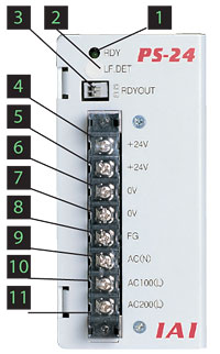
|
|||||||||||||||||||||||||||||||||||||||||||||||||||||||||||||
| Specification Table | |||||||||||||||||||||||||||||||||||||||||||||||||||||||||||||
Go to: |
|||||||||||||||||||||||||||||||||||||||||||||||||||||||||||||