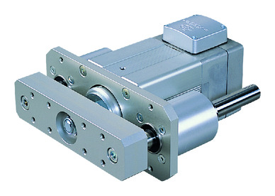
RCS2-SRGD7BD


*Note: Some pictures on this page are still Japanese version and the English version pictures are coming soon.
Main Specifications
| item | Contents | ||||||||||
|---|---|---|---|---|---|---|---|---|---|---|---|
| motor | Output (W) | 60W | 100W | 150W | |||||||
| Lead | Ball screw lead (mm) | 16 | 8 | 4 | 16 | 8 | 4 | 16 | 8 | 4 | |
| Horizontal | Payload capacity | Maximum payload (kg) | 5 | 10 | 20 | 10 | twenty two | 40 | 15 | 35 | 55 |
| Speed/Acceleration | Maximum speed (mm/s) | 800 | 400 | 200 | 800 | 400 | 200 | 800 | 400 | 200 | |
| Rated acceleration/deceleration (G) | 0.25 | 0.15 | 0.05 | 0.3 | 0.2 | 0.1 | 0.3 | 0.2 | 0.1 | ||
| Maximum acceleration/deceleration (G) | 0.35 | 0.25 | 0.15 | 0.4 | 0.3 | 0.2 | 0.4 | 0.3 | 0.2 | ||
| vertical | Payload capacity | Maximum payload (kg) | 1 | 4 | 9 | 2.5 | 8 | 18.5 | 5.5 | 13.5 | 21.5 |
| Speed/Acceleration | Maximum speed (mm/s) | 800 | 400 | 200 | 800 | 400 | 200 | 800 | 400 | 200 | |
| Rated acceleration/deceleration (G) | 0.25 | 0.15 | 0.05 | 0.3 | 0.2 | 0.1 | 0.3 | 0.2 | 0.1 | ||
| Maximum acceleration/deceleration (G) | 0.35 | 0.25 | 0.15 | 0.4 | 0.3 | 0.2 | 0.4 | 0.3 | 0.2 | ||
| Thrust | Rated thrust (N) | 63.4 | 126.8 | 253.7 | 103.5 | 207.0 | 413.9 | 156.9 | 313.8 | 627.5 | |
| brake | Brake Specifications | Non-excitation electromagnetic brake | |||||||||
| Brake holding force (kgf) | 1 | 4 | 9 | 2.5 | 8 | 18.5 | 5.5 | 13.5 | 21.5 | ||
| stroke | Minimum stroke (mm) | 50 | 50 | 50 | 50 | 50 | 50 | 50 | 50 | 50 | |
| Maximum stroke (mm) | 300 | 300 | 300 | 300 | 300 | 300 | 300 | 300 | 300 | ||
| Stroke pitch (mm) | 50 | 50 | 50 | 50 | 50 | 50 | 50 | 50 | 50 | ||
| item | Contents |
|---|---|
| Drive system | Ball screw φ12mm rolled C10 |
| Repeated positioning accuracy | ±0.02mm |
| Lost Motion | Less than 0.1 mm |
| rod | φ35mm Material: Aluminum with white anodized finish |
| Rod non-rotation accuracy | ±0.08 degrees |
| Ambient temperature and humidity | 0 to 40°C, 85% RH or less (no condensation) |
| Protection rating | IP30 |
| Vibration and shock resistance | 4.9m/ s2 |
| Overseas compatible standards | RoHS Directive |
| Motor Type | AC servo motor |
| Encoder Type | インクリメンタル |
| エンコーダーパルス数 | 3072 pulse/rev |
| 納期 | ホームページ[納期照会]に記載 |
Stroke and maximum speed
(Unit: mm/s)
| stroke Lead |
50 to 300 (in 50mm increments) |
|---|---|
| 16 | 800 |
| 8 | 400 |
| 4 | 200 |
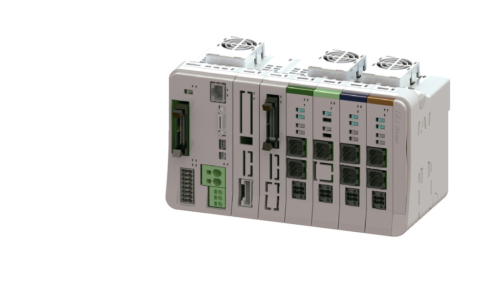
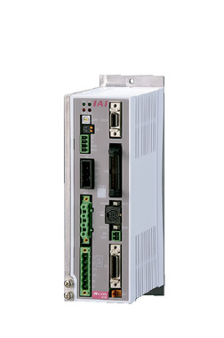
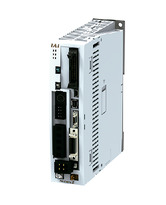
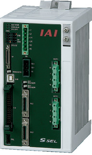
Adaptive Controller
The actuators on this page can be operated with the following controllers. Please select the type that suits your application.
| name | exterior | Maximum number of connectable axes |
Power supply voltage | Control Method | Maximum number of positioning points | ||||||||||||||
|---|---|---|---|---|---|---|---|---|---|---|---|---|---|---|---|---|---|---|---|
| Positioner | Pulse train | program | Network ※Select | ||||||||||||||||
| DV | CC | CIE | PR | CN | ML | ML3 | EC | EP | PRT | SSN | ECM | ||||||||
 |
16 (ML3, SSN, ECM are 8) |
DC24V Single-phase AC200V Three-phase AC200V |
- | - | - | ● | ● | ● | ● | - | - | ● | ● | ● | ● | ● | ● | 128 (ML3, SSN, ECM no position data) |
|
 |
8 | - | - | ● | ● | ● | ● | ● | - | - | - | ● | ● | ● | - | - | 36000 | ||
 |
1 | Single phase AC 100V/200V |
● | ● | - | ● | ● | ● | ● | ● | ● | ● | ● | ● | ● | - | ● | 512 (network specification is 768) |
|
 |
1 | Single phase AC100V | ● | ● | - | ● | ● | ● | - | - | - | ● | ● | ● | ● | - | - | 384 | |
 |
1 | Single phase AC200V | ● | ● | - | ● | ● | ● | - | - | - | ● | ● | ● | ● | - | - | 384 | |
 |
6 | Single-phase AC200V Three-phase AC200V |
- | - | ● | ● | ● | - | ● | - | - | - | - | ● | - | - | - | 20000 | |
(Note) For network abbreviations such as DV and CC, please see page
(Note) The 5th and 6th axes of XSEL-P/Q cannot be connected.
(Note) For ML3 and EC of SCON2, if there is no function option of the controller model, the remote I/O specification will be used. If "M" is selected as the function option, the motion network specification will be used.
International Standards

Selection considerations
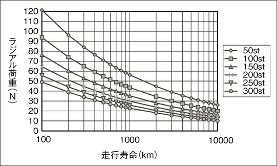
| (1) The maximum payload is the value when operating at the rated acceleration/deceleration. (2) The usable duty ratio varies depending on the operating conditions (payload, acceleration/deceleration, etc.). For details, see page . (3) The horizontal payload is the value when using an external guide and no external force is applied to the rod from any direction other than the direction of travel. For the usable mass of the included guide alone, see "Static allowable torque at the rod tip", "Relationship between tip allowable load and running life", and "Radial load and tip deflection". (4) Caution is required depending on the installation position. For details, see page . (5) Please note that due to the structure, it cannot be used with the home position reversed. |
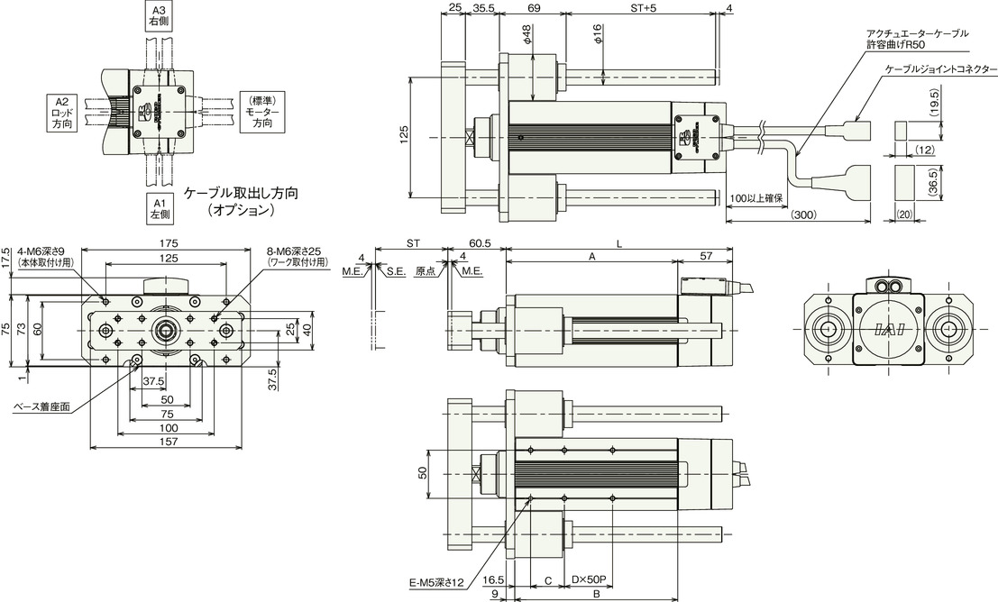
Dimensions
Standard Specifications
ST: Stroke
ME: Mechanical end
SE: Stroke end
(Note) The motor/encoder cable is connected to the cable joint connector. For details on the cable, see page
(Note) When returning to the origin, the rod moves to the ME, so be careful not to let it interfere with surrounding objects.
(Note) There are slits on the side of the main body to prevent breathing when moving forward and backward. Since dust may get inside the main body through these slits, please be careful when using in dusty environments.
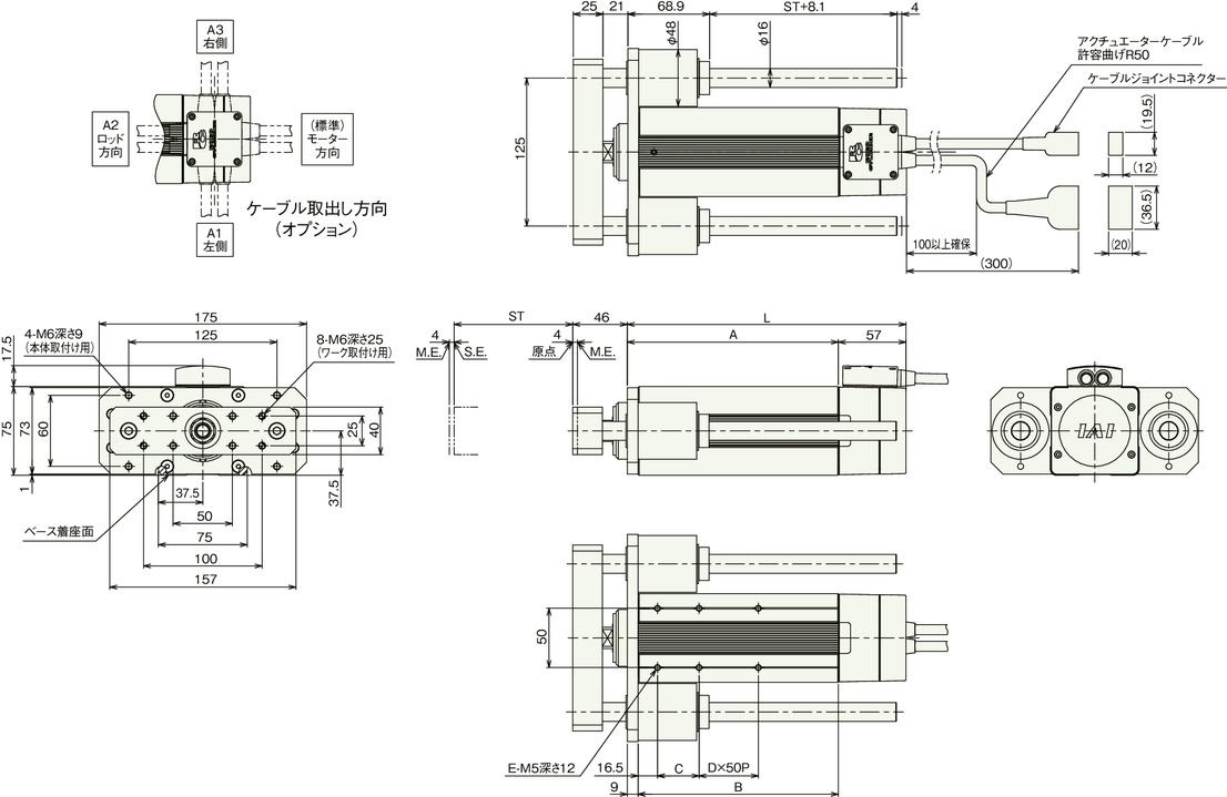
Stroke dimensions
| stroke | 50 | 100 | 150 | 200 | 250 | 300 | |
|---|---|---|---|---|---|---|---|
| L | 60W | 135 | 185 | 235 | 285 | 335 | 385 |
| 100W | 142 | 185 | 235 | 285 | 335 | 385 | |
| 150W | 154 | 185 | 235 | 285 | 335 | 385 | |
| A | 60W | 78 | 128 | 178 | 228 | 278 | 328 |
| 100W | 85 | 128 | 178 | 228 | 278 | 328 | |
| 150W | 97 | 128 | 178 | 228 | 278 | 328 | |
| B | 60W | 69 | 119 | 169 | 219 | 269 | 319 |
| 100W | 76 | 119 | 169 | 219 | 269 | 319 | |
| 150W | 88 | 119 | 169 | 219 | 269 | 319 | |
| C | twenty five | 35 | 35 | 35 | 35 | 35 | |
| D | 0 | 0 | 1 | 2 | 3 | 4 | |
| E | 4 | 4 | 6 | 8 | 10 | 12 | |
Mass by stroke
| stroke | 50 | 100 | 150 | 200 | 250 | 300 | |
|---|---|---|---|---|---|---|---|
| Mass (kg) |
No brake (60W) | 4.3 | 5.0 | 5.7 | 6.4 | 7.2 | 7.9 |
| No brake (100W) | 4.5 | 5.1 | 5.9 | 6.6 | 7.3 | 8.0 | |
| No brake (150W) | 4.8 | 5.3 | 6.1 | 6.8 | 7.5 | 8.2 | |
| With brake (60W) | 4.6 | 5.3 | 6.0 | 6.7 | 7.5 | 8.2 | |
| With brake (100W) | 4.8 | 5.4 | 6.2 | 6.9 | 7.6 | 8.3 | |
| With brake (150W) | 5.1 | 5.6 | 6.4 | 7.1 | 7.8 | 8.5 | |
Rod end extension specification
ST: Stroke
ME: Mechanical end
SE: Stroke end
(Note) The motor/encoder cable is connected to the cable joint connector. For details on the cable, see page
(Note) When returning to the origin, the rod moves to the ME, so be careful not to let it interfere with surrounding objects.
(Note) There are slits on the side of the main body to prevent breathing when moving forward and backward. Since dust may get inside the main body through these slits, please be careful when using in dusty environments.
Stroke dimensions
| stroke | 50 | 100 | 150 | 200 | 250 | 300 | |
|---|---|---|---|---|---|---|---|
| L | 60W | 135 | 185 | 235 | 285 | 335 | 385 |
| 100W | 142 | 185 | 235 | 285 | 335 | 385 | |
| 150W | 154 | 185 | 235 | 285 | 335 | 385 | |
| A | 60W | 78 | 128 | 178 | 228 | 278 | 328 |
| 100W | 85 | 128 | 178 | 228 | 278 | 328 | |
| 150W | 97 | 128 | 178 | 228 | 278 | 328 | |
| B | 60W | 69 | 119 | 169 | 219 | 269 | 319 |
| 100W | 76 | 119 | 169 | 219 | 269 | 319 | |
| 150W | 88 | 119 | 169 | 219 | 269 | 319 | |
| C | twenty five | 35 | 35 | 35 | 35 | 35 | |
| D | 0 | 0 | 1 | 2 | 3 | 4 | |
| E | 4 | 4 | 6 | 8 | 10 | 12 | |
Mass by stroke
| stroke | 50 | 100 | 150 | 200 | 250 | 300 | |
|---|---|---|---|---|---|---|---|
| Mass (kg) |
No brake (60W) | 4.3 | 5.0 | 5.7 | 6.4 | 7.2 | 7.9 |
| No brake (100W) | 4.5 | 5.1 | 5.9 | 6.6 | 7.3 | 8.0 | |
| No brake (150W) | 4.8 | 5.3 | 6.1 | 6.8 | 7.5 | 8.2 | |
| With brake (60W) | 4.6 | 5.3 | 6.0 | 6.7 | 7.5 | 8.2 | |
| With brake (100W) | 4.8 | 5.4 | 6.2 | 6.9 | 7.6 | 8.3 | |
| With brake (150W) | 5.1 | 5.6 | 6.4 | 7.1 | 7.8 | 8.5 | |
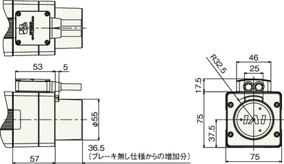
With brake
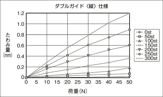
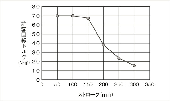
Rod tip static allowable torque, running life, tip deflection
Rod tip static allowable torque
Relationship between tip allowable load and running life
Radial load and tip deflection
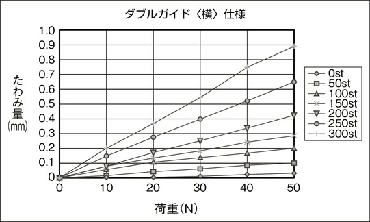
Radial load and tip deflection