RCS2-RGD4R


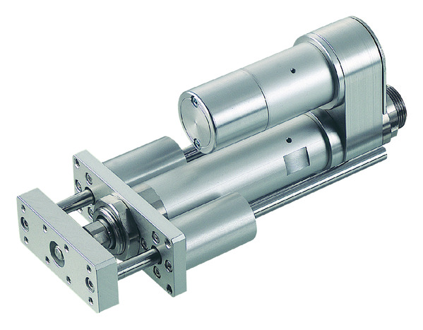
Actuator Specification
| Model | Motor power (W) |
Lead (mm) |
Maximum payload capacity | Rated thrust (N) |
Stroke (mm) |
|
|---|---|---|---|---|---|---|
| Level (kg) | Vertical (kg) | |||||
| RCS2-RGD4R-①-20-12-②-T2-③-④ | 20 | 12 | 3.0 | 0.5 | 18.9 | 50 to 300 (every 50 mm) |
| RCS2-RGD4R-①-20-6-②-T2-③-④ | 6 | 6.0 | 1.5 | 37.7 | ||
| RCS2-RGD4R-①-20-3-②-T2-③-④ | 3 | 12.0 | 3.5 | 75.4 | ||
| RCS2-RGD4R-①-30-12-②-T2-③-④ | 30 | 12 | 4.0 | 1.0 | 28.3 | |
| RCS2-RGD4R-①-30-6-②-T2-③-④ | 6 | 9.0 | 2.5 | 56.6 | ||
| RCS2-RGD4R-①-30-3-②-T2-③-④ | 3 | 18.0 | 6.0 | 113.1 | ||
Symbol explanation ① Encoder type ② Stroke ③ Cable length ④ Option
| stroke Lead |
50 to 300 (every 50 mm) |
|---|---|
| 12 | 600 |
| 6 | 300 |
| 3 | 150 |
(Unit: mm/s)
*Note: Some pictures on this page are still Japanese version and the English version pictures are coming soon.
Actuator Specifications
| item | Contents |
|---|---|
| Drive system | Ball screw φ10mm rolled C10 |
| Repeated positioning accuracy | ±0.02mm |
| Lost Motion | Less than 0.1 mm |
| Rod Diameter | φ20mm |
| Rod non-rotation accuracy | ±0.05 degrees |
| Ambient temperature and humidity | 0 to 40°C, 85% RH or less (no condensation) |
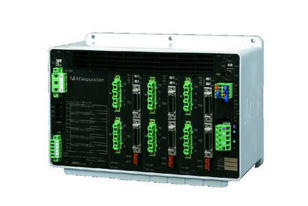
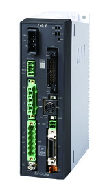
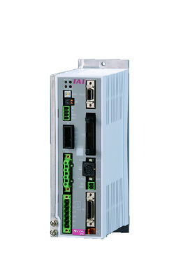
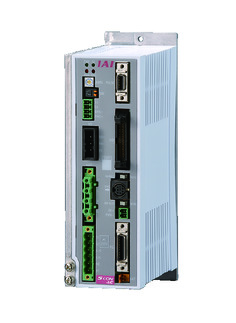
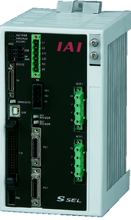
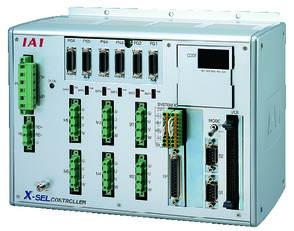
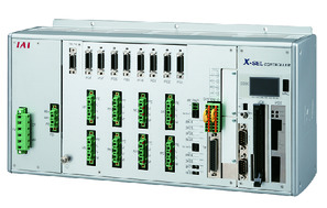
Adaptive Controller
The actuators on this page can be operated with the following controllers. Please select the type that suits your application.
| name | exterior | Maximum number of connectable axes |
Power supply voltage | Control Method | Maximum number of positioning points | ||||||||||||||
|---|---|---|---|---|---|---|---|---|---|---|---|---|---|---|---|---|---|---|---|
| Positioner | Pulse train | program | Network ※Select | ||||||||||||||||
| DV | CC | CIE | PR | CN | ML | ML3 | EC | EP | PRT | SSN | ECM | ||||||||
 |
6 | Single phase AC 100V/200V |
- | - | - | ● | ● | - | ● | ● | - | - | ● | ● | - | - | - | 256 | |
 |
1 | ● | - | - | ● | ● | - | ● | ● | ● | - | ● | ● | ● | - | - | 512 (network specification is 768) |
||
 |
1 | ● | ● | - | ● | ● | ● | ● | ● | ● | ● | ● | ● | ● | - | - | 512 (network specification is 768) |
||
 |
1 | - | - | ● | ● | ● | - | ● | ● | ● | - | ● | ● | ● | - | - | 512 (network specification is 768) |
||
 |
2 | ● | - | ● | ● | ● | - | ● | - | - | - | - | ● | - | - | - | 20000 | ||
 |
6 | Single-phase AC200V Three-phase AC200V |
- | - | ● | ● | ● | - | ● | - | - | - | - | ● | - | - | - | 20000 | |
 |
8 | - | - | ● | ● | ● | - | ● | - | - | - | ● | ● | - | - | - | 55000 (varies by type) |
||
(Note) For network abbreviations such as DV and CC, please see page
International Standards


(Note) CE is optional.
Selection considerations
| (1) The payload is the value when operating at an acceleration of 0.3 G (0.2 G for lead 3) and is the upper acceleration limit. (2) The usable duty will vary depending on the operating conditions (payload, acceleration/deceleration, etc.). For details, see page . (3) The horizontal payload is the value when used in conjunction with an external guide and no external forces are applied to the rod from any direction other than the direction of travel. For the usable weight of the included guide alone, see page . (4) Caution is required depending on the mounting position. For details, see page |
Dimensions
ST: Stroke
ME: Mechanical end
SE: Stroke end
*1 Connect the motor/encoder cable. For details on the cable, see page
*2 When performing a return to origin, the rod moves to the ME, so be careful not to interfere with surrounding objects.
(Note) The orientation of the width across flats varies depending on the product.
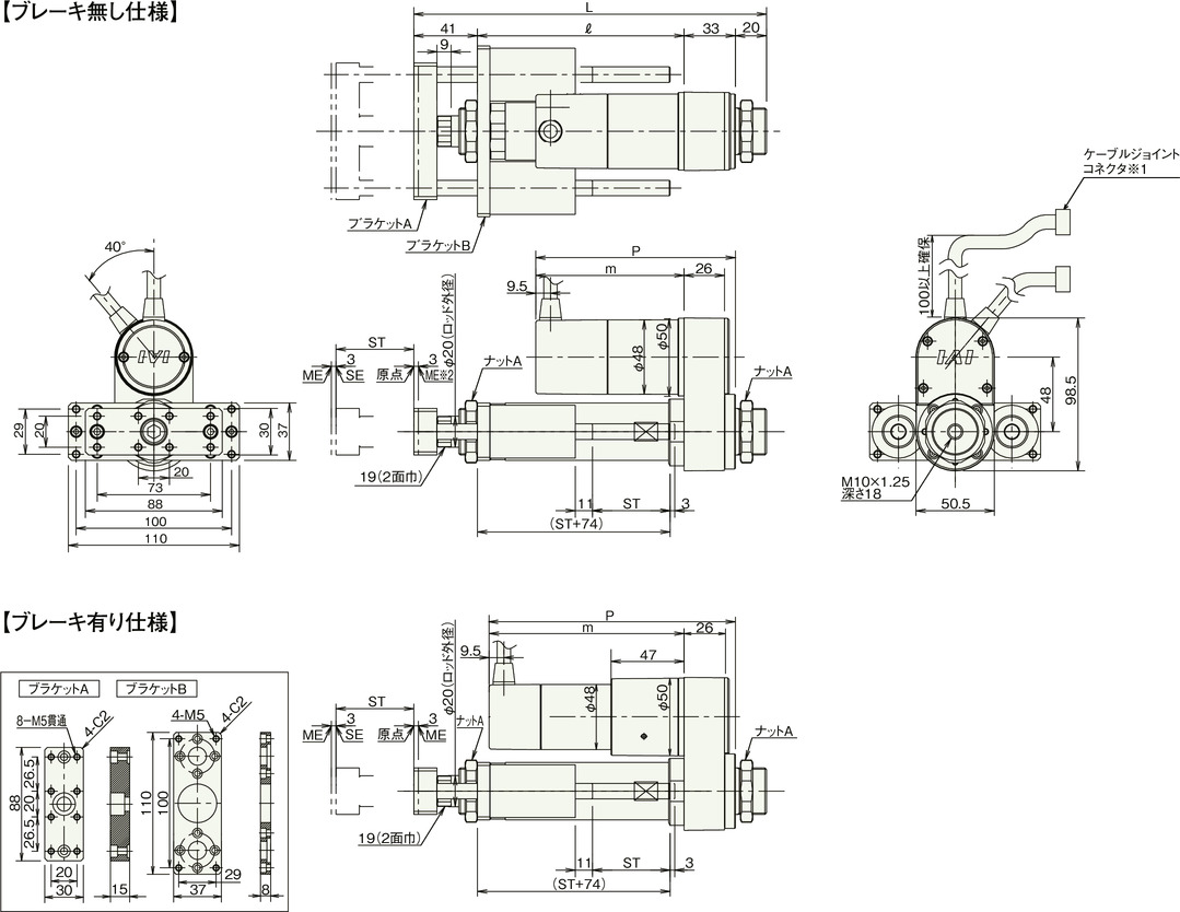
RCS2-RGD4R (without brake)
| stroke | 50 | 100 | 150 | 200 | 250 | 300 | |
|---|---|---|---|---|---|---|---|
| L | 20W | 227 | 277 | 327 | 377 | 427 | 477 |
| 30W | 227 | 277 | 327 | 377 | 427 | 477 | |
| ℓ | 133 | 183 | 233 | 283 | 333 | 383 | |
| m | 20W | 80.5 | |||||
| 30W | 95.5 | ||||||
| P | 20W | 113.5 | |||||
| 30W | 128.5 | ||||||
| Mass (kg) | 1.9 | 2.2 | 2.3 | 2.6 | 2.7 | 3.0 | |
RCS2-RGD4R (with brake)
| stroke | 50 | 100 | 150 | 200 | 250 | 300 | |
|---|---|---|---|---|---|---|---|
| L | 20W | 227 | 277 | 327 | 377 | 427 | 477 |
| 30W | 227 | 277 | 327 | 377 | 427 | 477 | |
| ℓ | 133 | 183 | 233 | 283 | 333 | 383 | |
| m | 20W | 123.5 | |||||
| 30W | 138.5 | ||||||
| P | 20W | 156.5 | |||||
| 30W | 171.5 | ||||||
| Mass (kg) | 2.1 | 2.4 | 2.5 | 2.8 | 2.9 | 3.2 | |