Powered by Google Translate
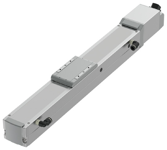
RCP6CR-HSA7C
High Rigidity Slider Type
Cleanroom Specification
Body Width : 80 mm
Product Features


Mounting position


* Webpage Translation Disclaimer (Please click here)
Main specifications
| item | Content | |||||
|---|---|---|---|---|---|---|
| Lead | Ball screw lead (mm) | 24 | 16 | 8 | 4 | |
| horizontal | Payload | Maximum payload (kg) (high output effective) | 37 | 48 | 61 | 55 |
| Maximum payload (kg) (high output disabled) | 18 | 35 | 40 | 40 | ||
| Speed/acceleration/deceleration | Maximum speed (mm/s) | 1230 | 840 | 420 | 210 | |
| Minimum speed (mm/s) | 30 | 20 | 10 | 5 | ||
| Rated acceleration/deceleration (G) | 0.3 | 0.1 | 0.1 | 0.1 | ||
| Maximum acceleration/deceleration (G) | 1 | 1 | 1 | 1 | ||
| vertical | Payload | Maximum payload (kg) (high output effective) | 3 | 8 | 16 | 25 |
| Maximum payload (kg) (high output disabled) | 2 | 5 | 10 | 15 | ||
| Speed/acceleration/deceleration | Maximum speed (mm/s) | 1080 | 840 | 420 | 210 | |
| Minimum speed (mm/s) | 30 | 20 | 10 | 5 | ||
| Rated acceleration/deceleration (G) | 0.3 | 0.3 | 0.3 | 0.3 | ||
| Maximum acceleration/deceleration (G) | 0.5 | 0.5 | 0.5 | 0.5 | ||
| Pressing | Maximum thrust when pressing (N) | 139 | 209 | 418 | 836 | |
| Maximum pressing speed (mm/s) | 20 | 20 | 20 | 20 | ||
| Clean room specifications | Vacuum volume (NL/min) | 130 | 80 | 50 | 30 | |
| brake | Brake specifications | Non-excitation electromagnetic brake | ||||
| Brake holding force (kgf) | 3 | 8 | 16 | 25 | ||
| stroke | Minimum stroke (mm) | 50 | 50 | 50 | 50 | |
| Maximum stroke (mm) | 800 | 800 | 800 | 800 | ||
| Stroke pitch (mm) | 50 | 50 | 50 | 50 | ||
| item | Content |
|---|---|
| Drive system | Ball screw φ12mm Rolled C10 |
| Repeated positioning accuracy (Note 3) | ±0.01mm 【±0.005mm】 |
| Lost Motion | 0.1mm or less |
| base | Material: Aluminum with white anodized finish |
| Linear guide | Direct acting infinite circulation type |
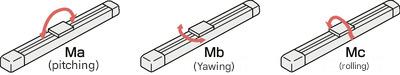
| Static allowable moment | Ma: 145 N・m |
| Mb: 145 N・m | |
| Mc: 300 N・m | |
| Dynamic allowable moment (Note 4) |
Ma: 75.5 N・m |
| Mb: 90 N・m | |
| Mc: 134 N・m | |
| Cleanliness | Class 2.5 equivalent (ISO 14644-1 standard) |
| Ambient temperature and humidity | 0 to 40°C, 85% RH or less (no condensation) |
| Protection class | IP20 |
| Vibration and shock resistance | 4.9 m/ s² |
| Overseas compatible standards | CE mark, RoHS directive |
| Motor Type | Pulse motor |
| Encoder Type | Battery-less absolute |
| Encoder pulse count | 8192 pulses/rev |
| deadline | Listed on the homepage [Delivery date inquiry] |
(Note 3) The values in brackets [ ] are for high precision specifications (leads 4, 8).
(Note 4) Based on a standard rated life of 5,000 km. Running life will vary depending on operating conditions and installation.Please refer to page 1-280 for details on running life.
Slider type moment direction
Stroke and maximum speed
(unit: mm/s)
| Lead (mm) |
Connection Controller |
50 to 500 (every 50 mm) |
550 (mm) |
600 (mm) |
650 (mm) |
700 (mm) |
750 (mm) |
800 (mm) |
|---|---|---|---|---|---|---|---|---|
| twenty four | High output enabled | 1230<1080> | 1080 | 950 | 840 | 750 | ||
| High Output Disabled | 800 | 750 | ||||||
| 16 | High output enabled | 840 | 820 | 715 | 625 | 555 | 495 | |
| High Output Disabled | 560 | 555 | 495 | |||||
| 8 | High output enabled | 420 | 405 | 350 | 310 | 275 | 245 | |
| High Output Disabled | 280 | 275 | 245 | |||||
| 4 | High output enabled | 210 | 195 | 175 | 150 | 135 | 120 | |
| High Output Disabled | 140<105> | 135<105> | 120<105> | |||||
(Note) The values in are for vertical use.
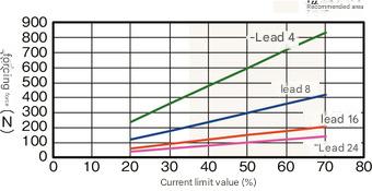
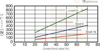
Correlation diagram between pressing force and current limit value
Payload capacity by speed and acceleration *High output setting is enabled at the time of shipment. For details, see page 1-23 .
High output setting enabled (power mode). Maximum speed varies depending on payload. Payload is in kg. Blank fields indicate non-operational.
| posture | horizontal | vertical | ||||||
|---|---|---|---|---|---|---|---|---|
| speed | Acceleration (G) | |||||||
| (mm/s) | 0.1 | 0.3 | 0.5 | 0.7 | 1 | 0.1 | 0.3 | 0.5 |
| 0 | 37 | 37 | 22 | 16 | 14 | 3 | 3 | 3 |
| 200 | 37 | 37 | 22 | 16 | 14 | 3 | 3 | 3 |
| 420 | 37 | 34 | 20 | 16 | 14 | 3 | 3 | 3 |
| 640 | 37 | 20 | 15 | 10 | 9 | 3 | 3 | 3 |
| 860 | 12 | 9 | 6 | 4 | 2 | 2 | ||
| 1080 | 6 | 3 | 1.5 | 0.5 | 0.5 | 0.5 | ||
| 1230 | 3 | 1 | ||||||
| posture | horizontal | vertical | ||||||
|---|---|---|---|---|---|---|---|---|
| speed | Acceleration (G) | |||||||
| (mm/s) | 0.1 | 0.3 | 0.5 | 0.7 | 1 | 0.1 | 0.3 | 0.5 |
| 0 | 48 | 46 | 35 | 28 | 27 | 8 | 8 | 8 |
| 140 | 48 | 46 | 35 | 28 | 27 | 8 | 8 | 8 |
| 280 | 48 | 46 | 35 | 25 | 24 | 8 | 8 | 8 |
| 420 | 46 | 34 | 25 | 15 | 10 | 6 | 5 | 4.5 |
| 560 | 35 | 20 | 15 | 10 | 6 | 5 | 4 | 3 |
| 700 | 20 | 14 | 8 | 5 | 2.5 | 3 | 1 | 1 |
| 840 | 6 | 2 | 0.5 | |||||
| posture | horizontal | vertical | ||||||
|---|---|---|---|---|---|---|---|---|
| speed | Acceleration (G) | |||||||
| (mm/s) | 0.1 | 0.3 | 0.5 | 0.7 | 1 | 0.1 | 0.3 | 0.5 |
| 0 | 61 | 55 | 50 | 45 | 40 | 16 | 16 | 16 |
| 70 | 61 | 55 | 50 | 45 | 40 | 16 | 16 | 16 |
| 140 | 61 | 55 | 50 | 45 | 37 | 16 | 16 | 16 |
| 210 | 61 | 55 | 40 | 33 | 24 | 11 | 10 | 9.5 |
| 280 | 55 | 40 | 28 | 20 | 13 | 9 | 8 | 7 |
| 350 | 51 | 21 | 9 | 4 | 7 | 4 | 3 | |
| 420 | 40 | 7 | 4 | 1 | ||||
| posture | horizontal | vertical | ||||||
|---|---|---|---|---|---|---|---|---|
| speed | Acceleration (G) | |||||||
| (mm/s) | 0.1 | 0.3 | 0.5 | 0.7 | 1 | 0.1 | 0.3 | 0.5 |
| 0 | 55 | 51 | 45 | 40 | 40 | 25 | 25 | 25 |
| 35 | 55 | 51 | 45 | 40 | 40 | 25 | 25 | 25 |
| 70 | 55 | 51 | 45 | 40 | 40 | 25 | 25 | 25 |
| 105 | 55 | 51 | 45 | 40 | 35 | 25 | 20 | 19 |
| 140 | 55 | 45 | 35 | 30 | 25 | 16 | 14 | 12 |
| 175 | 55 | 30 | 14 | 11 | 7 | 3 | ||
| 210 | 45 | 5 | ||||||
High output setting disabled (energy saving mode). Maximum speed varies depending on the payload. Payload is in kg. Blank fields indicate that the operation is not possible.
| posture | horizontal | vertical | |
|---|---|---|---|
| speed | Acceleration (G) | ||
| (mm/s) | 0.3 | 0.7 | 0.3 |
| 0 | 18 | 10 | 2 |
| 200 | 18 | 10 | 2 |
| 420 | 18 | 10 | 2 |
| 640 | 10 | 2 | 1 |
| 800 | 4 | 0.5 | 0.5 |
| posture | horizontal | vertical | |
|---|---|---|---|
| speed | Acceleration (G) | ||
| (mm/s) | 0.3 | 0.7 | 0.3 |
| 0 | 35 | 20 | 5 |
| 140 | 35 | 20 | 5 |
| 280 | 25 | 12 | 3 |
| 420 | 15 | 6 | 1.5 |
| 560 | 7 | 0.5 | 0.5 |
| posture | horizontal | vertical | |
|---|---|---|---|
| speed | Acceleration (G) | ||
| (mm/s) | 0.3 | 0.7 | 0.3 |
| 0 | 40 | 25 | 10 |
| 70 | 40 | 25 | 10 |
| 140 | 40 | 25 | 7 |
| 210 | 25 | 14 | 4 |
| 280 | 10 | 1.5 | |
| posture | horizontal | vertical | |
|---|---|---|---|
| speed | Acceleration (G) | ||
| (mm/s) | 0.3 | 0.7 | 0.3 |
| 0 | 40 | 30 | 15 |
| 35 | 40 | 30 | 15 |
| 70 | 40 | 30 | 15 |
| 105 | 40 | 30 | 8 |
| 140 | 3 | ||
Adaptive Controller
The actuators on this page can be operated with the following controllers. Please select the type that best suits your application.
| name | exterior | Maximum number of connectable axes |
Power supply voltage | Control Method | Maximum number of positioning points | |||||||||||||||
|---|---|---|---|---|---|---|---|---|---|---|---|---|---|---|---|---|---|---|---|---|
| Positioner | Pulse train | program | Network *Select | |||||||||||||||||
| DV | CC | CIE | CIT | PR | CN | ML | ML3 | EC | EP | PRT | SSN | ECM | ||||||||
| MSEL-PC/PG | 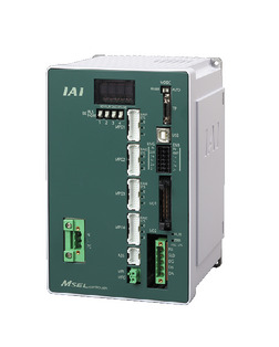 |
4 | Single-phase AC 100-230V |
- | - | ● | ● | ● | - | - | ● | - | - | - | ● | ● | ● | - | - | 30000 |
| PCON-CB/CGB | 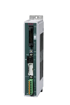 |
1 | DC24V | ● ※Select |
● ※Select |
- | ● | ● | ● | - | ● | ● | ● | ● | ● | ● | ● | - | - | 512 (network specification is 768) |
| PCON-CYB/PLB/POB | 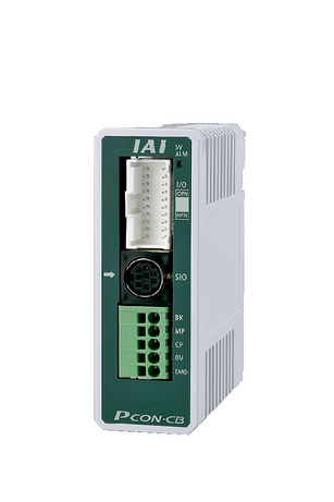 |
1 | ● ※Select |
● ※Select |
- | - | - | - | - | - | - | - | - | - | - | - | - | - | 64 | |
| RCON | 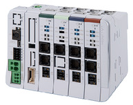 |
16 (ML3, SSN, ECM are 8) |
- | - | - | ● | ● | ● | ● | ● | - | - | ● | ● | ● | ● | ● | ● | 128 (ML3, SSN, ECM have no position data) |
|
| RSEL |  |
8 | - | - | ● | ● | ● | ● | - | ● | - | - | - | ● | ● | ● | - | - | 36000 | |
(Note) For network abbreviations such as DV and CC, please refer to page 8-15 .
Overseas Standards


Selection precautions
 |
(1)
As the stroke length increases, the maximum speed decreases due to the
critical rotation speed of the ball screw. Check the maximum speed for
your desired stroke in "Stroke and Maximum Speed." (2) The maximum load capacity is listed in "Main Specifications." For details, refer to the "Load Capacity by Speed and Acceleration Table." (3) For push-motion operations, refer to the "Correlation Diagram of Push Force and Current Limit Value." The push force is a guideline value. For important points, see page 1-321. (4) The duty ratio must be limited depending on the ambient temperature. For details, see page 1-334. (5) Caution is required depending on the mounting orientation. For details, see page 1-313. (6) The recommended overhang load length is 300 mm or less in the Ma, Mb, and Mc directions (600 mm or less for double slider specifications). For details on overhang load length, see page 7-78. (7) For double slider specifications, see page 1-299 for ordering model numbers and precautions . |
Dimensions
ST: Stroke
ME: Mechanical end
SE: Stroke end
(Note) When performing a return to origin, the slider will move to the ME, so be careful not to interfere with the surrounding area.
(Note) For details on precautions for changing the cable exit direction, refer to page 7-748 .
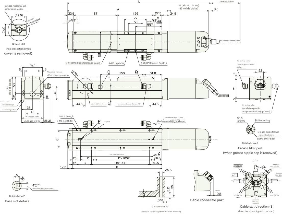
Stroke dimensions
| stroke | 50 | 100 | 150 | 200 | 250 | 300 | 350 | 400 | 450 | 500 | 550 | 600 | 650 | 700 | 750 | 800 | |
|---|---|---|---|---|---|---|---|---|---|---|---|---|---|---|---|---|---|
| L | No brakes | 396 | 446 | 496 | 546 | 596 | 646 | 696 | 746 | 796 | 846 | 896 | 946 | 996 | 1046 | 1096 | 1146 |
| With brake | 446 | 496 | 546 | 596 | 646 | 696 | 746 | 796 | 846 | 896 | 946 | 996 | 1046 | 1096 | 1146 | 1196 | |
| A | 250.5 | 300.5 | 350.5 | 400.5 | 450.5 | 500.5 | 550.5 | 600.5 | 650.5 | 700.5 | 750.5 | 800.5 | 850.5 | 900.5 | 950.5 | 1000.5 | |
| B | 208.5 | 258.5 | 308.5 | 358.5 | 408.5 | 458.5 | 508.5 | 558.5 | 608.5 | 658.5 | 708.5 | 758.5 | 808.5 | 858.5 | 908.5 | 958.5 | |
| C | 50 | 0 | 50 | 0 | 50 | 0 | 50 | 0 | 50 | 0 | 50 | 0 | 50 | 0 | 50 | 0 | |
| D | 1 | 2 | 2 | 3 | 3 | 4 | 4 | 5 | 5 | 6 | 6 | 7 | 7 | 8 | 8 | 9 | |
| E | 6 | 6 | 8 | 8 | 10 | 10 | 12 | 12 | 14 | 14 | 16 | 16 | 18 | 18 | 20 | 20 | |
| J | 150 | 200 | 250 | 300 | 350 | 400 | 450 | 500 | 550 | 600 | 650 | 700 | 750 | 800 | 850 | 900 | |
Mass by stroke
| stroke | 50 | 100 | 150 | 200 | 250 | 300 | 350 | 400 | 450 | 500 | 550 | 600 | 650 | 700 | 750 | 800 | |
|---|---|---|---|---|---|---|---|---|---|---|---|---|---|---|---|---|---|
| Mass (kg) |
No brakes | 3.8 | 4.0 | 4.3 | 4.6 | 4.8 | 5.1 | 5.4 | 5.6 | 5.9 | 6.2 | 6.4 | 6.7 | 7.0 | 7.2 | 7.5 | 7.8 |
| With brake | 4.3 | 4.5 | 4.8 | 5.1 | 5.3 | 5.6 | 5.9 | 6.1 | 6.4 | 6.7 | 6.9 | 7.2 | 7.5 | 7.7 | 8.0 | 8.3 | |
Main specifications (double slider specification)
| item | Content | ||||
|---|---|---|---|---|---|
| Lead | Ball screw lead (mm) | 16 | 8 | 4 | |
| horizontal | Payload | Maximum payload (kg) (high output effective) | 44 | 49 | 49 |
| Maximum payload (kg) (high output disabled) | 33 | 38 | 38 | ||
| Speed/acceleration/deceleration | Maximum speed (mm/s) | 560 | 420 | 175 | |
| Minimum speed (mm/s) | 20 | 10 | 5 | ||
| Rated acceleration/deceleration (G) | 0.3 | 0.3 | 0.3 | ||
| Maximum acceleration/deceleration (G) | 1 | 1 | 1 | ||
| vertical | Payload | Maximum payload (kg) (high output effective) | - | 14 | 23 |
| Maximum payload (kg) (high output disabled) | - | 8 | 13 | ||
| Speed/acceleration/deceleration | Maximum speed (mm/s) | - | 350 | 175 | |
| Minimum speed (mm/s) | - | 10 | 5 | ||
| Rated acceleration/deceleration (G) | - | 0.3 | 0.3 | ||
| Maximum acceleration/deceleration (G) | - | 0.5 | 0.5 | ||
| Pressing | Maximum thrust when pressing (N) | 112 | 224 | 449 | |
| Maximum pressing speed (mm/s) | 20 | 20 | 20 | ||
| Clean room specifications | Vacuum volume (NL/min) | 100 | 60 | 40 | |
| brake | Brake specifications | Non-excitation electromagnetic brake | |||
| Brake holding force (kgf) | 2.5 | 6 | 16 | ||
| stroke | Minimum nominal stroke (mm) | 200 | 200 | 200 | |
| Minimum effective stroke (mm) | 50 | 50 | 50 | ||
| Maximum nominal stroke (mm) | 800 | 800 | 800 | ||
| Maximum effective stroke (mm) | 650 | 650 | 650 | ||
| Stroke pitch (mm) | 50 | 50 | 50 | ||
(Note) Nominal stroke: The stroke listed in the model number
Effective stroke: The stroke that can actually be operated
(Note) Lead 16 cannot be installed vertically.
| item | Content |
|---|---|
| Drive system | Ball screw φ12mm Rolled C10 |
| Repeated positioning accuracy | ±0.01mm |
| Lost Motion | 0.1mm or less |
| base | Material: Aluminum with white anodized finish |
| Linear guide | Direct acting infinite circulation type |
| Static allowable moment | Ma: 900 N・m |
| Mb: 900 N・m | |
| Mc: 458 N・m | |
| Dynamic allowable moment (Note 5) |
Ma: 316 N・m |
| Mb: 376 N・m | |
| Mc: 218 N・m | |
| Cleanliness | Class 2.5 equivalent (ISO 14644-1 standard) |
| Ambient temperature and humidity | 0 to 40°C, 85% RH or less (no condensation) |
| Protection class | IP20 |
| Vibration and shock resistance | 4.9 m/ s² |
| Overseas compatible standards | CE mark, RoHS directive |
| Motor Type | Pulse motor |
| Encoder Type | Battery-less absolute |
| Encoder pulse count | 8192 pulses/rev |
| deadline | Listed on the homepage [Delivery date inquiry] |
(Note 5) Based on a standard rated life of 5,000 km. Running life will vary depending on operating conditions and installation. 1-280 for details on running life.
Slider type moment direction
Payload capacity by speed and acceleration (double slider specification) *High output setting is enabled at the time of shipment. For details, see page 1-23 .
High output setting enabled (power mode). Maximum speed varies depending on payload. Payload is in kg. Blank fields indicate non-operational.
| posture | horizontal | vertical | ||||
|---|---|---|---|---|---|---|
| speed | Acceleration (G) | |||||
| (mm/s) | 0.3 | 0.5 | 0.7 | 1 | 0.3 | 0.5 |
| 0 | 44 | 33 | 26 | 25 | ||
| 140 | 44 | 33 | 26 | 25 | ||
| 280 | 44 | 32 | 22 | 20 | ||
| 420 | 30 | 20 | 10 | 6 | ||
| 560 | 10 | 6 | 4 | 2 | ||
| posture | horizontal | vertical | ||||
|---|---|---|---|---|---|---|
| speed | Acceleration (G) | |||||
| (mm/s) | 0.3 | 0.5 | 0.7 | 1 | 0.3 | 0.5 |
| 0 | 49 | 43 | 38 | 38 | 14 | 14 |
| 70 | 49 | 43 | 38 | 38 | 14 | 14 |
| 140 | 49 | 38 | 36 | 33 | 14 | 14 |
| 210 | 49 | 33 | 28 | 20 | 8 | 7 |
| 280 | 36 | 24 | 16 | 10 | 5 | 4 |
| 350 | 14 | 4 | 1 | 1 | ||
| 420 | 3 | |||||
| posture | horizontal | vertical | ||||
|---|---|---|---|---|---|---|
| speed | Acceleration (G) | |||||
| (mm/s) | 0.3 | 0.5 | 0.7 | 1 | 0.3 | 0.5 |
| 0 | 49 | 43 | 38 | 38 | 23 | 23 |
| 35 | 49 | 43 | 38 | 38 | 23 | 23 |
| 70 | 49 | 43 | 38 | 38 | 23 | 23 |
| 105 | 49 | 43 | 38 | 33 | 18 | 17 |
| 140 | 40 | 30 | 25 | 20 | 9 | 7 |
| 175 | 25 | 7 | 4 | 1 | ||
High output setting disabled (energy saving mode). Maximum speed varies depending on the payload. Payload is in kg. Blank fields indicate that the operation is not possible.
| posture | horizontal | vertical | |
|---|---|---|---|
| speed | Acceleration (G) | ||
| (mm/s) | 0.3 | 0.7 | 0.3 |
| 0 | 33 | 18 | |
| 140 | 33 | 18 | |
| 280 | 23 | 10 | |
| 420 | 10 | 3 | |
| posture | horizontal | vertical | |
|---|---|---|---|
| speed | Acceleration (G) | ||
| (mm/s) | 0.3 | 0.7 | 0.3 |
| 0 | 38 | 23 | 8 |
| 70 | 38 | 23 | 8 |
| 140 | 38 | 23 | 5 |
| 210 | 20 | 10 | 2 |
| 280 | 5 | ||
| posture | horizontal | vertical | |
|---|---|---|---|
| speed | Acceleration (G) | ||
| (mm/s) | 0.3 | 0.7 | 0.3 |
| 0 | 38 | 28 | 13 |
| 35 | 38 | 28 | 13 |
| 70 | 38 | 28 | 13 |
| 105 | 36 | 26 | 4 |
| 140 | 6 | ||
Stroke and maximum speed (double slider specification)
(unit: mm/s)
| Lead (mm) |
Nominal stroke | 200 to 550 | 600 | 650 | 700 | 750 | 800 |
|---|---|---|---|---|---|---|---|
| Effective stroke | 50 to 400 | 450 | 500 | 550 | 600 | 650 | |
| Connection Controller |
(every 50mm) | (mm) | (mm) | (mm) | (mm) | (mm) | |
| 16 | High output enabled | 560 | 555 | 495 | |||
| High Output Disabled | 420 | ||||||
| 8 | High output enabled | 420<350> | 405<350> | 350 | 310 | 275 | 245 |
| High Output Disabled | 280<210> | 275<210> | 245<210> | ||||
| 4 | High output enabled | 175 | 150 | 135 | 120 | ||
| High Output Disabled | 140<105> | 135<105> | 120<105> | ||||
(Note) The values in are for vertical use.
(Note) Nominal stroke: The stroke listed in the model number
Effective stroke: The stroke that can actually be operated
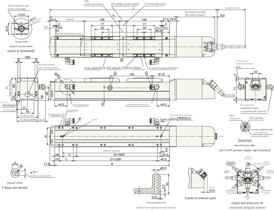
Dimensions (double slider specification)
ST: Stroke
ME: Mechanical end
SE: Stroke end
Drawing (double slider specification)
(Note) When returning to the origin, the slider will move to the ME, so be careful not to let it interfere with surrounding objects.
(Note) For details on precautions for changing the cable exit direction, refer to page 7-748 .
Stroke dimensions
| Nominal stroke | 200 | 250 | 300 | 350 | 400 | 450 | 500 | 550 | 600 | 650 | 700 | 750 | 800 | |
|---|---|---|---|---|---|---|---|---|---|---|---|---|---|---|
| Effective stroke | 50 | 100 | 150 | 200 | 250 | 300 | 350 | 400 | 450 | 500 | 550 | 600 | 650 | |
| L | No brakes | 546 | 596 | 646 | 696 | 746 | 796 | 846 | 896 | 946 | 996 | 1046 | 1096 | 1146 |
| With brake | 596 | 646 | 696 | 746 | 796 | 846 | 896 | 946 | 996 | 1046 | 1096 | 1146 | 1196 | |
| A | 400.5 | 450.5 | 500.5 | 550.5 | 600.5 | 650.5 | 700.5 | 750.5 | 800.5 | 850.5 | 900.5 | 950.5 | 1000.5 | |
| B | 358.5 | 408.5 | 458.5 | 508.5 | 558.5 | 608.5 | 658.5 | 708.5 | 758.5 | 808.5 | 858.5 | 908.5 | 958.5 | |
| C | 0 | 50 | 0 | 50 | 0 | 50 | 0 | 50 | 0 | 50 | 0 | 50 | 0 | |
| D | 3 | 3 | 4 | 4 | 5 | 5 | 6 | 6 | 7 | 7 | 8 | 8 | 9 | |
| E | 8 | 10 | 10 | 12 | 12 | 14 | 14 | 16 | 16 | 18 | 18 | 20 | 20 | |
| J | 300 | 350 | 400 | 450 | 500 | 550 | 600 | 650 | 700 | 750 | 800 | 850 | 900 | |
(Note) Nominal stroke: The stroke listed in the model number
Effective stroke: The stroke that can actually be operated
Mass by stroke
| Nominal stroke | 200 | 250 | 300 | 350 | 400 | 450 | 500 | 550 | 600 | 650 | 700 | 750 | 800 | |
|---|---|---|---|---|---|---|---|---|---|---|---|---|---|---|
| Effective stroke | 50 | 100 | 150 | 200 | 250 | 300 | 350 | 400 | 450 | 500 | 550 | 600 | 650 | |
| Mass (kg) |
No brakes | 5.33 | 5.53 | 5.83 | 6.13 | 6.33 | 6.63 | 6.93 | 7.13 | 7.43 | 7.73 | 7.93 | 8.23 | 8.53 |
| With brake | 5.83 | 6.03 | 6.33 | 6.63 | 6.83 | 7.13 | 7.43 | 7.63 | 7.93 | 8.23 | 8.43 | 8.73 | 9.03 | |
(Note) This is the mass of the single slider model plus a 0.73 kg free slider.
Correlation diagram between pressing force and current limit value (double slider specification)
(Note) This is the same value as the single slider specification.
Webpage Translation Disclaimer
This is an English translation of the original Japanese version of this webpage. This translation has been generated by an automatic machine translation service for your convenience.
While we make reasonable efforts to provide an accurate translation, no automated translation is perfect. The machine translation may contain errors, omissions, or inaccuracies and is not intended to replace human translation.
Please be aware of the following:
- No Guarantee of Accuracy: We do not guarantee the accuracy, reliability, or correctness of the content provided by the machine translation. Any person or entity that relies on the information obtained from this translated version does so at their own risk.
- Authoritative Version: In the event of any discrepancies or differences created in the translation, the original Japanese version of the webpage is the official and authoritative text.
- Limited Translation Scope: Certain content, such as images containing text, PDF files, graphics, and specific applications, may not be accurately translated or may not be translated at all due to the limitations of the translation software.
- Exclusion of Liability: We shall not be liable for any loss, damage, or other problems, whether direct or indirect, that may result from the use or performance of the machine-translated content.