RCP6-HSA7R


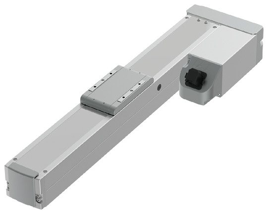
(Note) The photo above shows the motor left-folded specification (ML).
*Note: Some pictures on this page are still Japanese version and the English version pictures are coming soon.
Main Specifications
| item | Contents | |||||
|---|---|---|---|---|---|---|
| Lead | Ball screw lead (mm) | 24 | 16 | 8 | 4 | |
| Horizontal | Payload capacity | Maximum payload (kg) (high output effective) | 37 | 48 | 53 | 53 |
| Maximum payload (kg) (high output disabled) | 18 | 35 | 40 | 40 | ||
| Speed/Acceleration | Maximum speed (mm/s) | 1080 | 700 | 350 | 175 | |
| Minimum speed (mm/s) | 30 | 20 | 10 | 5 | ||
| Rated acceleration/deceleration (G) | 0.3 | 0.1 | 0.1 | 0.1 | ||
| Maximum acceleration/deceleration (G) | 1 | 1 | 1 | 1 | ||
| vertical | Payload capacity | Maximum payload (kg) (high output effective) | 3 | 8 | 16 | 25 |
| Maximum payload (kg) (high output disabled) | 2 | 5 | 10 | 15 | ||
| Speed/Acceleration | Maximum speed (mm/s) | 860 | 560 | 350 | 140 | |
| Minimum speed (mm/s) | 30 | 20 | 10 | 5 | ||
| Rated acceleration/deceleration (G) | 0.3 | 0.3 | 0.3 | 0.3 | ||
| Maximum acceleration/deceleration (G) | 0.5 | 0.5 | 0.5 | 0.5 | ||
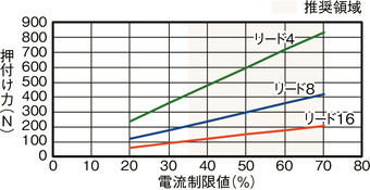
| Pressing | Maximum thrust when pressing (N) | 139 | 209 | 418 | 836 | |
| Maximum pressing speed (mm/s) | 30 | 30 | 20 | 20 | ||
| brake | Brake Specifications | Non-excitation electromagnetic brake | ||||
| Brake holding force (kgf) | 3 | 8 | 16 | 25 | ||
| stroke | Minimum stroke (mm) | 50 | 50 | 50 | 50 | |
| Maximum stroke (mm) | 800 | 800 | 800 | 800 | ||
| Stroke pitch (mm) | 50 | 50 | 50 | 50 | ||
| item | Contents |
|---|---|
| Drive system | Ball screw φ12mm rolled C10 |
| Repeated positioning accuracy | ±0.01mm |
| Lost Motion | Less than 0.1 mm |
| base | Material: Aluminum, white anodized |
| Linear guide | Direct-acting infinite circulation type |
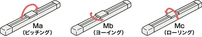
| Static allowable moment | Ma: 145 N・m |
| Mb: 145 N・m | |
| Mc: 300 N・m | |
| Dynamic allowable moment (Note 3) |
Ma: 75.5 N・m |
| Mb: 90 N・m | |
| Mc: 134 N・m | |
| Ambient temperature and humidity | 0 to 40°C, 85% RH or less (no condensation) |
| Protection rating | IP20 |
| Vibration and shock resistance | 4.9m/ s2 |
| Overseas compatible standards | CE mark, RoHS directive |
| Motor Type | Pulse motor |
| Encoder Type | Battery-less absolute |
| Encoder Pulse Number | 8192 pulses/rev |
| deadline | Listed on the website [Delivery Date Inquiry] |
(Note 3) Based on a standard rated life of 5,000 km. The running life will vary depending on the operating conditions and installation. Please check the running life on page
Slider type moment direction

Stroke and maximum speed
(Unit: mm/s)
| Lead (mm) |
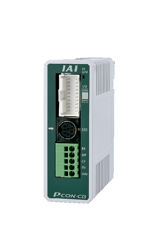
Connection Controller |
50 to 650 (in 50mm increments) |
700 (mm) |
750 (mm) |
800 (mm) |
|---|---|---|---|---|---|
| 24 | High output enabled | 1080<860> | 950<860> | 840 | 750 |
| High output disabled | 800<640> | 750<640> | |||
| 16 | High output enabled | 700<560> | 625<560> | 555 | 495 |
| High output disabled | 500<420> | 495<420> | |||
| 8 | High output enabled | 350 | 310 | 275 | 245 |
| High output disabled | 210 | ||||
| 4 | High output enabled | 175<140> | 150<140> | 135 | 120 |
| High output disabled | 120<105> | ||||
(Note) Values in < > are for vertical use.
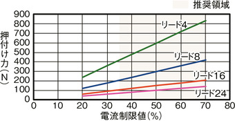
Correlation diagram between pressing force and current limit value
Payload capacity by speed and acceleration *High output setting is enabled at the time of shipment. For details, see page 1-23 .
High output setting enabled (power mode) The maximum speed varies depending on the payload. The payload is in kg. Blank spaces indicate that the operation is not possible.
| posture | Horizontal | vertical | ||||||
|---|---|---|---|---|---|---|---|---|
| speed | Acceleration (G) | |||||||
| (mm/s) | 0.1 | 0.3 | 0.5 | 0.7 | 1 | 0.1 | 0.3 | 0.5 |
| 0 | 37 | 37 | 22 | 16 | 14 | 3 | 3 | 3 |
| 200 | 37 | 37 | 22 | 16 | 14 | 3 | 3 | 3 |
| 420 | 34 | 34 | 20 | 16 | 11 | 3 | 3 | 3 |
| 640 | 15 | 15 | 10 | 8 | 6.5 | 3 | 3 | 2 |
| 860 | 9 | 6 | 3 | 2 | 1 | 0.5 | ||
| 1080 | 3 | |||||||
| posture | Horizontal | vertical | ||||||
|---|---|---|---|---|---|---|---|---|
| speed | Acceleration (G) | |||||||
| (mm/s) | 0.1 | 0.3 | 0.5 | 0.7 | 1 | 0.1 | 0.3 | 0.5 |
| 0 | 48 | 46 | 35 | 28 | 27 | 8 | 8 | 8 |
| 140 | 48 | 46 | 35 | 28 | 27 | 8 | 8 | 8 |
| 280 | 48 | 46 | 35 | 25 | 19 | 8 | 8 | 8 |
| 420 | 35 | 30 | 19 | 15 | 10 | 5 | 5 | 4.5 |
| 560 | 15 | 15 | 9 | 5 | 2 | 2.5 | 2.5 | 2 |
| 700 | 3 | 3 | 1 | |||||
| posture | Horizontal | vertical | ||||||
|---|---|---|---|---|---|---|---|---|
| speed | Acceleration (G) | |||||||
| (mm/s) | 0.1 | 0.3 | 0.5 | 0.7 | 1 | 0.1 | 0.3 | 0.5 |
| 0 | 53 | 51 | 45 | 40 | 40 | 16 | 16 | 16 |
| 70 | 53 | 51 | 45 | 40 | 40 | 16 | 16 | 16 |
| 140 | 53 | 51 | 40 | 38 | 35 | 16 | 16 | 16 |
| 210 | 51 | 51 | 35 | 30 | 24 | 9 | 9 | 8 |
| 280 | 35 | 35 | 20 | 15 | 9 | 6 | 6 | 5 |
| 350 | 11 | 11 | 1 | 1 | 1 | |||
| posture | Horizontal | vertical | ||||||
|---|---|---|---|---|---|---|---|---|
| speed | Acceleration (G) | |||||||
| (mm/s) | 0.1 | 0.3 | 0.5 | 0.7 | 1 | 0.1 | 0.3 | 0.5 |
| 0 | 53 | 51 | 45 | 40 | 40 | 25 | 25 | 25 |
| 35 | 53 | 51 | 45 | 40 | 40 | 25 | 25 | 25 |
| 70 | 53 | 51 | 45 | 40 | 40 | 25 | 25 | 25 |
| 105 | 51 | 51 | 45 | 40 | 35 | 20 | 20 | 19 |
| 140 | 45 | 45 | 25 | 10 | 6 | 12.5 | 12.5 | 7 |
| 175 | 11 | |||||||
High output setting disabled (energy saving mode) The maximum speed varies depending on the payload. The payload is in kg. Blank spaces indicate that the operation is not possible.
| posture | Horizontal | vertical | |
|---|---|---|---|
| speed | Acceleration (G) | ||
| (mm/s) | 0.3 | 0.7 | 0.3 |
| 0 | 18 | 10 | 2 |
| 200 | 18 | 10 | 2 |
| 420 | 18 | 10 | 2 |
| 640 | 9 | 2 | 1 |
| 800 | 1 | ||
| posture | Horizontal | vertical | |
|---|---|---|---|
| speed | Acceleration (G) | ||
| (mm/s) | 0.3 | 0.7 | 0.3 |
| 0 | 35 | 20 | 5 |
| 140 | 35 | 20 | 5 |
| 280 | 25 | 12 | 3 |
| 420 | 14 | 4 | 1.5 |
| 500 | 4 | ||
| posture | Horizontal | vertical | |
|---|---|---|---|
| speed | Acceleration (G) | ||
| (mm/s) | 0.3 | 0.7 | 0.3 |
| 0 | 40 | 25 | 10 |
| 70 | 40 | 25 | 10 |
| 140 | 40 | 25 | 7 |
| 210 | 25 | 14 | 4 |
| posture | Horizontal | vertical | |
|---|---|---|---|
| speed | Acceleration (G) | ||
| (mm/s) | 0.3 | 0.7 | 0.3 |
| 0 | 40 | 30 | 15 |
| 35 | 40 | 30 | 15 |
| 70 | 40 | 30 | 15 |
| 105 | 40 | 20 | 8 |
| 120 | 8 | ||
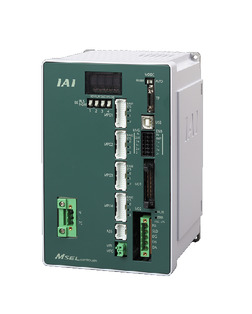
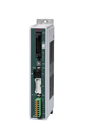
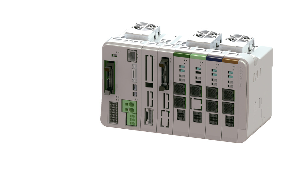
Adaptive Controller
The actuators on this page can be operated with the following controllers. Please select the type that suits your application.
| name | exterior | Maximum number of connectable axes |
Power supply voltage | Control Method | Maximum number of positioning points | ||||||||||||||
|---|---|---|---|---|---|---|---|---|---|---|---|---|---|---|---|---|---|---|---|
| Positioner | Pulse train | program | Network ※Select | ||||||||||||||||
| DV | CC | CIE | PR | CN | ML | ML3 | EC | EP | PRT | SSN | ECM | ||||||||
 |
4 | Single phase AC 100-230V |
- | - | ● | ● | ● | - | ● | - | - | - | ● | ● | ● | - | - | 30000 | |
 |
1 | DC24V | ● ※Select |
● ※Select |
- | ● | ● | ● | ● | ● | ● | ● | ● | ● | ● | - | - | 512 (network specification is 768) |
|
 |
1 | ● ※Select |
● ※Select |
- | - | - | - | - | - | - | - | - | - | - | - | - | 64 | ||
 |
16 (ML3, SSN, ECM are 8) |
- | - | - | ● | ● | ● | ● | - | - | ● | ● | ● | ● | ● | ● | 128 (ML3, SSN, ECM no position data) |
||
 |
8 | - | - | ● | ● | ● | ● | ● | - | - | - | ● | ● | ● | - | - | 36000 | ||
(Note) For network abbreviations such as DV and CC, please see page
International Standards


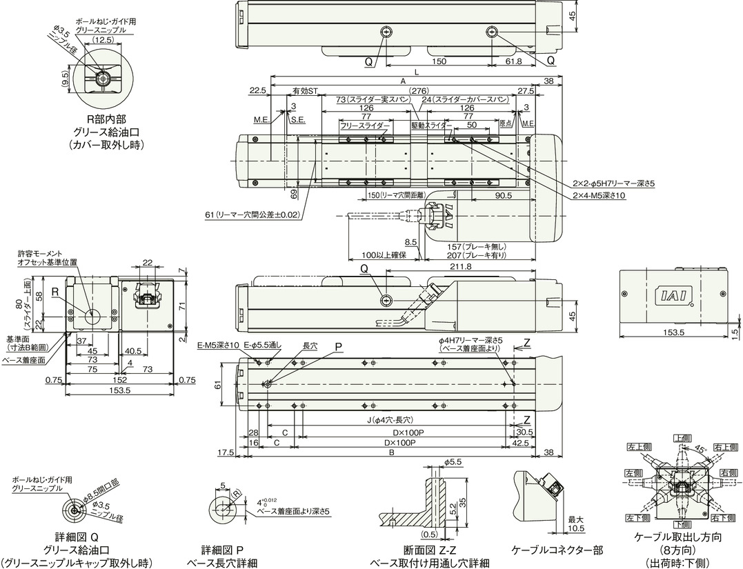
Dimensions
ST: Stroke
ME: Mechanical end
SE: Stroke end
(Note) When performing origin return, the slider will move to the ME, so please be careful not to interfere with the surroundings.
(Note) The diagram below shows the motor left-side reverse specification (ML).
(Note) For details on precautions for changing the cable exit direction, refer to page
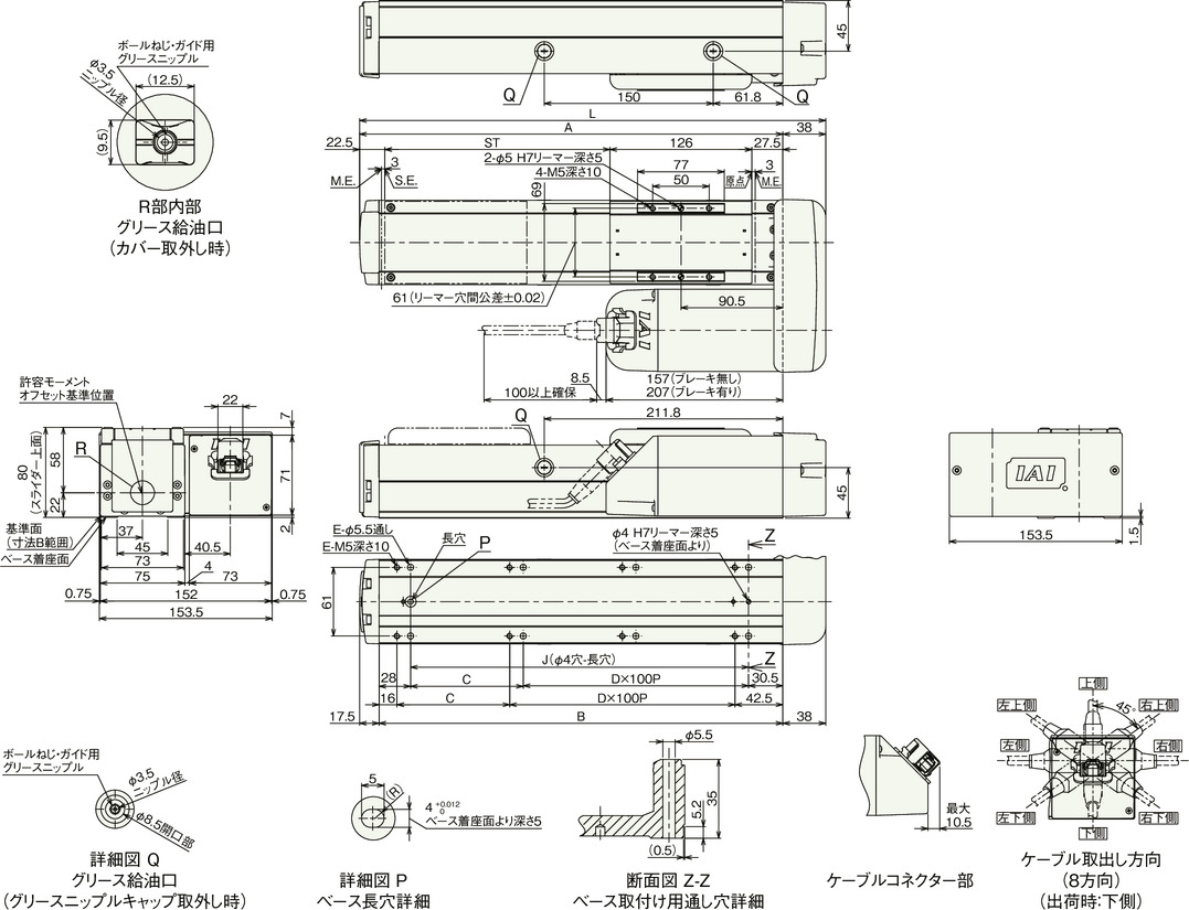
Stroke dimensions
| stroke | 50 | 100 | 150 | 200 | 250 | 300 | 350 | 400 | 450 | 500 | 550 | 600 | 650 | 700 | 750 | 800 |
|---|---|---|---|---|---|---|---|---|---|---|---|---|---|---|---|---|
| L | 264 | 314 | 364 | 414 | 464 | 514 | 564 | 614 | 664 | 714 | 764 | 814 | 864 | 914 | 964 | 1014 |
| A | 226 | 276 | 326 | 376 | 426 | 476 | 526 | 576 | 626 | 676 | 726 | 776 | 826 | 876 | 926 | 976 |
| B | 208.5 | 258.5 | 308.5 | 358.5 | 408.5 | 458.5 | 508.5 | 558.5 | 608.5 | 658.5 | 708.5 | 758.5 | 808.5 | 858.5 | 908.5 | 958.5 |
| C | 50 | 0 | 50 | 0 | 50 | 0 | 50 | 0 | 50 | 0 | 50 | 0 | 50 | 0 | 50 | 0 |
| D | 1 | 2 | 2 | 3 | 3 | 4 | 4 | 5 | 5 | 6 | 6 | 7 | 7 | 8 | 8 | 9 |
| E | 6 | 6 | 8 | 8 | 10 | 10 | 12 | 12 | 14 | 14 | 16 | 16 | 18 | 18 | 20 | 20 |
| J | 150 | 200 | 250 | 300 | 350 | 400 | 450 | 500 | 550 | 600 | 650 | 700 | 750 | 800 | 850 | 900 |
Mass by stroke
| stroke | 50 | 100 | 150 | 200 | 250 | 300 | 350 | 400 | 450 | 500 | 550 | 600 | 650 | 700 | 750 | 800 | |
|---|---|---|---|---|---|---|---|---|---|---|---|---|---|---|---|---|---|
| Mass (kg) |
No brakes | 4.3 | 4.5 | 4.8 | 5.0 | 5.3 | 5.6 | 5.8 | 6.1 | 6.4 | 6.6 | 6.9 | 7.1 | 7.4 | 7.7 | 7.9 | 8.2 |
| With brake | 4.8 | 5.0 | 5.3 | 5.5 | 5.8 | 6.1 | 6.3 | 6.6 | 6.9 | 7.1 | 7.4 | 7.6 | 7.9 | 8.2 | 8.4 | 8.7 | |
Main specifications (double slider specifications)
| item | Contents | ||||
|---|---|---|---|---|---|
| Lead | Ball screw lead (mm) | 16 | 8 | 4 | |
| Horizontal | Payload capacity | Maximum payload (kg) (high output effective) | 44 | 49 | 49 |
| Maximum payload (kg) (high output disabled) | 33 | 38 | 38 | ||
| Speed/Acceleration | Maximum speed (mm/s) | 560 | 280 | 140 | |
| Minimum speed (mm/s) | 20 | 10 | 5 | ||
| Rated acceleration/deceleration (G) | 0.3 | 0.3 | 0.3 | ||
| Maximum acceleration/deceleration (G) | 1 | 1 | 1 | ||
| vertical | Payload capacity | Maximum payload (kg) (high output effective) | - | 14 | 23 |
| Maximum payload (kg) (high output disabled) | - | 8 | 13 | ||
| Speed/Acceleration | Maximum speed (mm/s) | - | 210 | 105 | |
| Minimum speed (mm/s) | - | 10 | 5 | ||
| Rated acceleration/deceleration (G) | - | 0.3 | 0.3 | ||
| Maximum acceleration/deceleration (G) | - | 0.5 | 0.5 | ||
| Pressing | Maximum thrust when pressing (N) | 209 | 418 | 836 | |
| Maximum pressing speed (mm/s) | 20 | 20 | 20 | ||
| brake | Brake Specifications | Non-excitation electromagnetic brake | |||
| Brake holding force (kgf) | 2.5 | 6 | 16 | ||
| stroke | Minimum nominal stroke (mm) | 200 | 200 | 200 | |
| Minimum effective stroke (mm) | 50 | 50 | 50 | ||
| Maximum nominal stroke (mm) | 800 | 800 | 800 | ||
| Maximum effective stroke (mm) | 650 | 650 | 650 | ||
| Stroke pitch (mm) | 50 | 50 | 50 | ||
(Note) Nominal stroke: Model stroke
Effective stroke: The stroke that can actually be operated
(Note) Lead 12 cannot be installed vertically.
| item | Contents |
|---|---|
| Drive system | Ball screw φ12mm rolled C10 |
| Repeated positioning accuracy | ±0.01mm |
| Lost Motion | Less than 0.1 mm |
| base | Material: Aluminum, white anodized |
| Linear guide | Direct-acting infinite circulation type |
| Static allowable moment | Ma: 900 N・m |
| Mb: 900 N・m | |
| Mc: 458 N・m | |
| Dynamic allowable moment (Note 4) |
Ma: 316 N・m |
| Mb: 376 N・m | |
| Mc: 218 N・m | |
| Ambient temperature and humidity | 0 to 40°C, 85% RH or less (no condensation) |
| Protection rating | IP20 |
| Vibration and shock resistance | 4.9m/ s2 |
| Overseas compatible standards | CE mark, RoHS directive |
| Motor Type | Pulse motor |
| Encoder Type | Battery-less absolute |
| Encoder Pulse Number | 8192 pulses/rev |
| deadline | Listed on the website [Delivery Date Inquiry] |
(Note 4) Based on a standard rated life of 5,000 km. The running life will vary depending on the operating conditions and installation. Please check the running life on page
Slider type moment direction
Payload capacity by speed and acceleration (double slider specifications) *High output setting is enabled at the time of shipment. For details, please refer to page 1-23 .
High output setting enabled (power mode) The maximum speed varies depending on the payload. The payload is in kg. Blank spaces indicate that the operation is not possible.
| posture | Horizontal | vertical | ||||
|---|---|---|---|---|---|---|
| speed | Acceleration (G) | |||||
| (mm/s) | 0.3 | 0.5 | 0.7 | 1 | 0.3 | 0.5 |
| 0 | 44 | 33 | 26 | 25 | ||
| 140 | 44 | 33 | 26 | 25 | ||
| 280 | 44 | 32 | 22 | 20 | ||
| 420 | 22 | 15 | 8 | 6 | ||
| 560 | 5 | 3 | ||||
| posture | Horizontal | vertical | ||||
|---|---|---|---|---|---|---|
| speed | Acceleration (G) | |||||
| (mm/s) | 0.3 | 0.5 | 0.7 | 1 | 0.3 | 0.5 |
| 0 | 49 | 43 | 38 | 38 | 14 | 14 |
| 70 | 49 | 43 | 38 | 38 | 14 | 14 |
| 140 | 49 | 38 | 36 | 33 | 14 | 14 |
| 210 | 47 | 31 | 26 | 18 | 5 | 3.5 |
| 280 | 29 | 14 | ||||
| posture | Horizontal | vertical | ||||
|---|---|---|---|---|---|---|
| speed | Acceleration (G) | |||||
| (mm/s) | 0.3 | 0.5 | 0.7 | 1 | 0.3 | 0.5 |
| 0 | 49 | 43 | 38 | 38 | 23 | 23 |
| 35 | 49 | 43 | 38 | 38 | 23 | 23 |
| 70 | 49 | 43 | 38 | 38 | 23 | 23 |
| 105 | 49 | 43 | 36 | 31 | 16 | 15 |
| 140 | 38 | 21 | ||||
High output setting disabled (energy saving mode) The maximum speed varies depending on the payload. The payload is in kg. Blank spaces indicate that the operation is not possible.
| posture | Horizontal | vertical | |
|---|---|---|---|
| speed | Acceleration (G) | ||
| (mm/s) | 0.3 | 0.7 | 0.3 |
| 0 | 33 | 18 | |
| 140 | 33 | 18 | |
| 280 | 23 | 10 | |
| 420 | 8 | 1 | |
| posture | Horizontal | vertical | |
|---|---|---|---|
| speed | Acceleration (G) | ||
| (mm/s) | 0.3 | 0.7 | 0.3 |
| 0 | 38 | 23 | 8 |
| 70 | 38 | 23 | 8 |
| 140 | 38 | 23 | 5 |
| 210 | 18 | 8 | |
| posture | Horizontal | vertical | |
|---|---|---|---|
| speed | Acceleration (G) | ||
| (mm/s) | 0.3 | 0.7 | 0.3 |
| 0 | 38 | 28 | 13 |
| 35 | 38 | 28 | 13 |
| 70 | 38 | 28 | 13 |
| 105 | 36 | 26 | 4 |
| 120 | 4 | ||
Stroke and maximum speed (double slider specification)
(Unit: mm/s)
| Lead (mm) |
Nominal stroke | 200 to 700 | 750 | 800 |
|---|---|---|---|---|
| Effective Stroke | 50-550 | 600 | 650 | |
| Connection Controller |
(every 50mm) | (mm) | (mm) | |
| 16 | High output enabled | 560 | 555 | 495 |
| High output disabled | 420 | |||
| 8 | High output enabled | 280<210> | 275<210> | 245<210> |
| High output disabled | 210<140> | |||
| 4 | High output enabled | 140<105> | 135<105> | 120<105> |
| High output disabled | 120<105> | |||
(Note) Values in < > are for vertical use.
(Note) Nominal stroke: The stroke listed in the model number.
Effective stroke: The stroke that can actually be operated
Dimensions (double slider type)
ST: Stroke
ME: Mechanical end
SE: Stroke end
Drawing (double slider specification)
(Note) When performing origin return, the slider moves to the ME, so be careful not to let it interfere with surrounding objects.
(Note) The diagram below shows the motor left-side reverse specification (ML).
Stroke dimensions
| Nominal stroke | 200 | 250 | 300 | 350 | 400 | 450 | 500 | 550 | 600 | 650 | 700 | 750 | 800 |
|---|---|---|---|---|---|---|---|---|---|---|---|---|---|
| Effective Stroke | 50 | 100 | 150 | 200 | 250 | 300 | 350 | 400 | 450 | 500 | 550 | 600 | 650 |
| L | 414 | 464 | 514 | 564 | 614 | 664 | 714 | 764 | 814 | 864 | 914 | 964 | 1014 |
| A | 376 | 426 | 476 | 526 | 576 | 626 | 676 | 726 | 776 | 826 | 876 | 926 | 976 |
| B | 358.5 | 408.5 | 458.5 | 508.5 | 558.5 | 608.5 | 658.5 | 708.5 | 758.5 | 808.5 | 858.5 | 908.5 | 958.5 |
| C | 0 | 50 | 0 | 50 | 0 | 50 | 0 | 50 | 0 | 50 | 0 | 50 | 0 |
| D | 3 | 3 | 4 | 4 | 5 | 5 | 6 | 6 | 7 | 7 | 8 | 8 | 9 |
| E | 8 | 10 | 10 | 12 | 12 | 14 | 14 | 16 | 16 | 18 | 18 | 20 | 20 |
| J | 300 | 350 | 400 | 450 | 500 | 550 | 600 | 650 | 700 | 750 | 800 | 850 | 900 |
(Note) Nominal stroke: The stroke listed in the model number.
Effective stroke: The stroke that can actually be operated
Mass by stroke
| Nominal stroke | 200 | 250 | 300 | 350 | 400 | 450 | 500 | 550 | 600 | 650 | 700 | 750 | 800 | |
|---|---|---|---|---|---|---|---|---|---|---|---|---|---|---|
| Effective Stroke | 50 | 100 | 150 | 200 | 250 | 300 | 350 | 400 | 450 | 500 | 550 | 600 | 650 | |
| Mass (kg) |
No brakes | 5.73 | 6.03 | 6.33 | 6.53 | 6.83 | 7.13 | 7.33 | 7.63 | 7.83 | 8.13 | 8.43 | 8.63 | 8.93 |
| With brake | 6.23 | 6.53 | 6.83 | 7.03 | 7.33 | 7.63 | 7.83 | 8.13 | 8.33 | 8.63 | 8.93 | 9.13 | 9.43 | |
(Note) Mass is the sum of the single slider specification and the free slider (0.73 kg).
Correlation diagram between pressing force and current limit value (double slider specification)
(Note) Same value as the single slider specification.