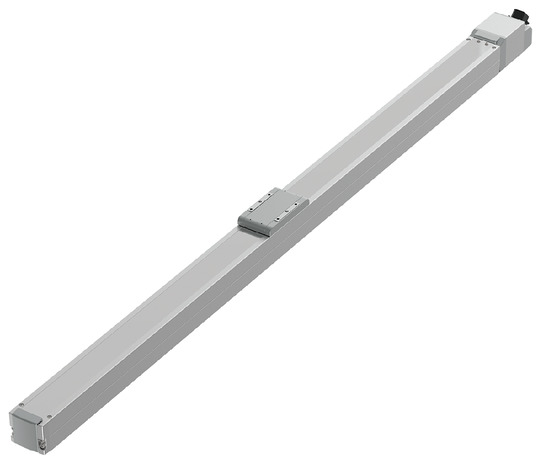
RCP6-HSA6XC


*Note: Some pictures on this page are still Japanese version and the English version pictures are coming soon.
Main Specifications
| item | Contents | |||||
|---|---|---|---|---|---|---|
| Lead | Ball screw lead (mm) | 20 | 12 | 6 | 3 | |
| Horizontal | Payload capacity | Maximum payload (kg) (high output effective) | 15 | 28 | 42 | 42 |
| Maximum payload (kg) (high output disabled) | 8 | 14 | 20 | 25 | ||
| Speed/Acceleration | Maximum speed (mm/s) | 1120 | 800 | 400 | 200 | |
| Minimum speed (mm/s) | 25 | 15 | 8 | 4 | ||
| Rated acceleration/deceleration (G) | 0.3 | 0.1 | 0.1 | 0.3 | ||
| Maximum acceleration/deceleration (G) | 1 | 1 | 1 | 1 | ||
| vertical | Payload capacity | Maximum payload (kg) (high output effective) | 1 | 2.5 | 6 | 16 |
| Maximum payload (kg) (high output disabled) | 0.75 | 2 | 5 | 10 | ||
| Speed/Acceleration | Maximum speed (mm/s) | 960 | 700 | 400 | 200 | |
| Minimum speed (mm/s) | 25 | 15 | 8 | 4 | ||
| Rated acceleration/deceleration (G) | 0.3 | 0.3 | 0.3 | 0.3 | ||
| Maximum acceleration/deceleration (G) | 0.5 | 0.5 | 0.5 | 0.5 | ||
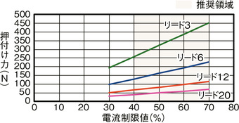
| Pressing | Maximum thrust when pressing (N) | 67 | 112 | 224 | 449 | |
| Maximum pressing speed (mm/s) | 30 | 30 | 20 | 20 | ||
| brake | Brake Specifications | Non-excitation electromagnetic brake | ||||
| Brake holding force (kgf) | 1 | 2.5 | 6 | 16 | ||
| stroke | Minimum stroke (mm) | 500 | 500 | 500 | 500 | |
| Maximum stroke (mm) | 1500 | 1500 | 1400 | 1000 | ||
| Stroke pitch (mm) | 50 | 50 | 50 | 50 | ||
| item | Contents |
|---|---|
| Drive system | Ball screw φ10mm rolled C10 |
| Repeated positioning accuracy | ±0.01mm |
| Lost Motion | Less than 0.1 mm |
| base | Material: Aluminum, white anodized |
| Linear guide | Direct-acting infinite circulation type |
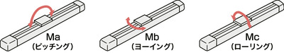
| Static allowable moment | Ma: 65 N・m |
| Mb: 75 N・m | |
| Mc: 120 N・m | |
| Dynamic allowable moment (Note 1) |
Ma: 33.7 N・m |
| Mb: 40.2 N・m | |
| Mc: 55.3 N・m | |
| Ambient temperature and humidity | 0 to 40°C, 85% RH or less (no condensation) |
| Protection rating | IP20 |
| Vibration and shock resistance | 4.9m/ s2 |
| Overseas compatible standards | CE mark, RoHS directive |
| Motor Type | Pulse motor |
| Encoder Type | Battery-less absolute |
| Encoder Pulse Number | 8192 pulses/rev |
| deadline | Listed on the website [Delivery Date Inquiry] |
(Note 1) Based on a standard rated life of 5,000 km. The running life will vary depending on the operating conditions and installation. Please check the running life on page
Slider type moment direction
Stroke and maximum speed
(Unit: mm/s)
| Lead (mm) |
Connection Controller |
500 to 700 (in 50mm increments) |
750 (mm) |
800 (mm) |
850 (mm) |
900 (mm) |
950 (mm) |
1000 (mm) |
1050 (mm) |
1100 (mm) |
1150 (mm) |
1200 (mm) |
1250 (mm) |
1300 (mm) |
1350 (mm) |
1400 (mm) |
1450 (mm) |
1500 (mm) |
|---|---|---|---|---|---|---|---|---|---|---|---|---|---|---|---|---|---|---|
| 20 | High output enabled | 1120 <960> | 970<960> | 940 | 860 | 790 | 730 | 640 | 610 | 580 | 540 | 470 | 450 | 430 | 400 | |||
| High output disabled | 800<640> | 790<640> | 730<640> | 640 | 610 | 580 | 540 | 470 | 450 | 430 | 400 | |||||||
| 12 | High output enabled | 800<700> | 770<700> | 680 | 620 | 560 | 510 | 460 | 425 | 380 | 360 | 330 | 315 | 285 | 270 | 250 | 235 | 220 |
| High output disabled | 560 | 510 | 460 | 425 | 380 | 360 | 330 | 315 | 285 | 270 | 250 | 235 | 220 | |||||
| 6 | High output enabled | 400 | 380 | 340 | 310 | 280 | 255 | 230 | 210 | 185 | 175 | 165 | 140 | 135 | 125 | 115 | ||
| High output disabled | 340<280> | 310<280> | 280 | 255 | 230 | 210 | 185 | 175 | 165 | 140 | 135 | 125 | 115 | |||||
| 3 | High output enabled | 200 | 190 | 165 | 145 | 135 | 125 | 115 | ||||||||||
| High output disabled | 140 | 135 | 125 | 115 | ||||||||||||||
(Note) <> indicates vertical use. Blank indicates non-operational.
Correlation diagram between pressing force and current limit value
Payload capacity by speed and acceleration *High output setting is enabled at the time of shipment. For details, see page 1-23 .
High output setting enabled (power mode) The maximum speed varies depending on the payload. The payload is in kg. Blank spaces indicate that the operation is not possible.
| posture | Horizontal | vertical | ||||||
|---|---|---|---|---|---|---|---|---|
| speed | Acceleration (G) | |||||||
| (mm/s) | 0.1 | 0.3 | 0.5 | 0.7 | 1 | 0.1 | 0.3 | 0.5 |
| 0 | 15 | 15 | 10 | 8 | 7 | 1 | 1 | 1 |
| 160 | 15 | 15 | 10 | 8 | 7 | 1 | 1 | 1 |
| 320 | 12 | 12 | 10 | 8 | 6 | 1 | 1 | 1 |
| 480 | 12 | 12 | 9 | 8 | 6 | 1 | 1 | 1 |
| 640 | 12 | 12 | 6.5 | 5 | 4 | 1 | 1 | 1 |
| 800 | 9.5 | 9.5 | 5 | 3 | 2 | 1 | 1 | 1 |
| 960 | 7 | 3 | 2 | 1 | 0.5 | 0.5 | ||
| 1120 | 5 | 1 | ||||||
| posture | Horizontal | vertical | ||||||
|---|---|---|---|---|---|---|---|---|
| speed | Acceleration (G) | |||||||
| (mm/s) | 0.1 | 0.3 | 0.5 | 0.7 | 1 | 0.1 | 0.3 | 0.5 |
| 0 | 28 | 26 | 18 | 16 | 14 | 2.5 | 2.5 | 2.5 |
| 80 | 28 | 26 | 18 | 16 | 14 | 2.5 | 2.5 | 2.5 |
| 200 | 28 | 26 | 18 | 16 | 14 | 2.5 | 2.5 | 2.5 |
| 320 | 26 | 26 | 18 | 14 | 12 | 2.5 | 2.5 | 2.5 |
| 440 | 26 | 26 | 13 | 11 | 8 | 2.5 | 2.5 | 2.5 |
| 560 | 17.5 | 17.5 | 9 | 5 | 3 | 2 | 2 | 2 |
| 700 | 9 | 3 | 2 | 1 | 1 | 0.5 | ||
| 800 | 3 | |||||||
| posture | Horizontal | vertical | ||||||
|---|---|---|---|---|---|---|---|---|
| speed | Acceleration (G) | |||||||
| (mm/s) | 0.1 | 0.3 | 0.5 | 0.7 | 1 | 0.1 | 0.3 | 0.5 |
| 0 | 42 | 38 | 26 | 24 | 20 | 6 | 6 | 6 |
| 40 | 42 | 38 | 26 | 24 | 20 | 6 | 6 | 6 |
| 100 | 40 | 38 | 26 | 24 | 20 | 6 | 6 | 6 |
| 160 | 40 | 38 | 26 | 24 | 20 | 6 | 6 | 6 |
| 220 | 37 | 36 | 26 | 24 | 18 | 6 | 6 | 6 |
| 280 | 32 | 32 | 25 | 17 | 13 | 6 | 6 | 5.5 |
| 340 | 22 | 22 | 11 | 6 | 5 | 4 | 4 | 3 |
| 400 | 12 | 6 | 2 | 2 | ||||
| posture | Horizontal | vertical | ||||||
|---|---|---|---|---|---|---|---|---|
| speed | Acceleration (G) | |||||||
| (mm/s) | 0.1 | 0.3 | 0.5 | 0.7 | 1 | 0.1 | 0.3 | 0.5 |
| 0 | 42 | 42 | 35 | 35 | 35 | 16 | 16 | 16 |
| 50 | 42 | 42 | 35 | 35 | 35 | 16 | 16 | 16 |
| 80 | 40 | 40 | 35 | 35 | 30 | 16 | 16 | 16 |
| 110 | 40 | 40 | 35 | 35 | 30 | 16 | 16 | 16 |
| 140 | 40 | 40 | 35 | 30 | 15 | 15 | 15 | 12 |
| 170 | 40 | 40 | 20 | 10 | 2 | 6 | 6 | 5 |
| 200 | 10 | 1 | 1 | |||||
High output setting disabled (energy saving mode) The maximum speed varies depending on the payload. The payload is in kg. Blank spaces indicate that the operation is not possible.
| posture | Horizontal | vertical | |
|---|---|---|---|
| speed | Acceleration (G) | ||
| (mm/s) | 0.3 | 0.7 | 0.3 |
| 0 | 8 | 5 | 0.75 |
| 160 | 8 | 5 | 0.75 |
| 320 | 8 | 5 | 0.75 |
| 480 | 8 | 4 | 0.75 |
| 640 | 6 | 3 | 0.75 |
| 800 | 3 | 0.5 | |
| posture | Horizontal | vertical | |
|---|---|---|---|
| speed | Acceleration (G) | ||
| (mm/s) | 0.3 | 0.7 | 0.3 |
| 0 | 14 | 10 | 2 |
| 80 | 14 | 10 | 2 |
| 200 | 14 | 10 | 2 |
| 320 | 14 | 10 | 2 |
| 440 | 11 | 5 | 1.5 |
| 560 | 4 | 0.5 | 0.5 |
| posture | Horizontal | vertical | |
|---|---|---|---|
| speed | Acceleration (G) | ||
| (mm/s) | 0.3 | 0.7 | 0.3 |
| 0 | 20 | 14 | 5 |
| 40 | 20 | 14 | 5 |
| 100 | 20 | 14 | 5 |
| 160 | 20 | 14 | 5 |
| 220 | 16 | 14 | 4 |
| 280 | 11 | 3 | 1.5 |
| 340 | 1 | ||
| posture | Horizontal | vertical | |
|---|---|---|---|
| speed | Acceleration (G) | ||
| (mm/s) | 0.3 | 0.7 | 0.3 |
| 0 | 25 | 22 | 10 |
| 20 | 25 | 22 | 10 |
| 50 | 25 | 22 | 10 |
| 80 | 25 | 22 | 10 |
| 110 | 20 | 14 | 8 |
| 140 | 15 | 4 | 3 |
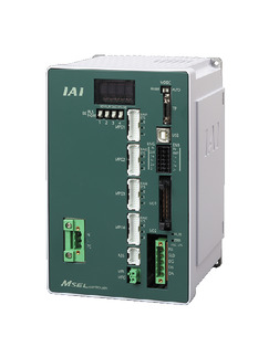
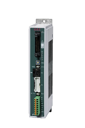
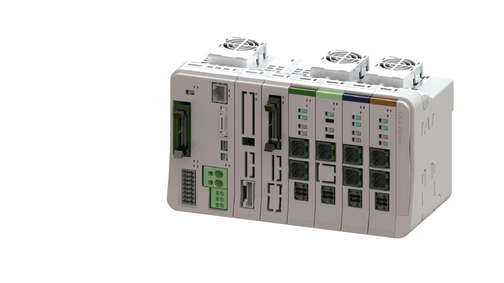
Adaptive Controller
The actuators on this page can be operated with the following controllers. Please select the type that suits your application.
| name | exterior | Maximum number of connectable axes |
Power supply voltage | Control Method | Maximum number of positioning points | ||||||||||||||
|---|---|---|---|---|---|---|---|---|---|---|---|---|---|---|---|---|---|---|---|
| Positioner | Pulse train | program | Network ※Select | ||||||||||||||||
| DV | CC | CIE | PR | CN | ML | ML3 | EC | EP | PRT | SSN | ECM | ||||||||
 |
4 | Single phase AC 100-230V |
- | - | ● | ● | ● | - | ● | - | - | - | ● | ● | ● | - | - | 30000 | |
 |
1 | DC24V | ● ※Select |
● ※Select |
- | ● | ● | ● | ● | ● | ● | ● | ● | ● | ● | - | - | 512 (network specification is 768) |
|
 |
1 | ● ※Select |
● ※Select |
- | - | - | - | - | - | - | - | - | - | - | - | - | 64 | ||
 |
16 (ML3, SSN, ECM are 8) |
- | - | - | ● | ● | ● | ● | - | - | ● | ● | ● | ● | ● | ● | 128 (ML3, SSN, ECM no position data) |
||
 |
8 | - | - | ● | ● | ● | ● | ● | - | - | - | ● | ● | ● | - | - | 36000 | ||
(Note) For network abbreviations such as DV and CC, please see page
International Standards


Selection considerations
| (1) As the stroke becomes longer, the maximum speed decreases due to the critical speed of the ball screw. Check the maximum speed for the desired stroke in "Stroke and maximum speed". (2) The maximum load capacity is shown in "Main specifications". For details, refer to "Load capacity by speed and acceleration table". (3) When performing a pressing operation, refer to "Correlation diagram of pressing force and current limit value". The pressing force is a guideline value. For points of caution, refer to page . (4) The duty ratio must be limited depending on the ambient temperature. For details, refer to page . (5) Caution is required depending on the mounting position. For details, refer to page . (6) The guideline for the overhang load length is 300 mm or less in the Ma, Mb, and Mc directions. For details on the overhang load length, refer to the explanation on page |
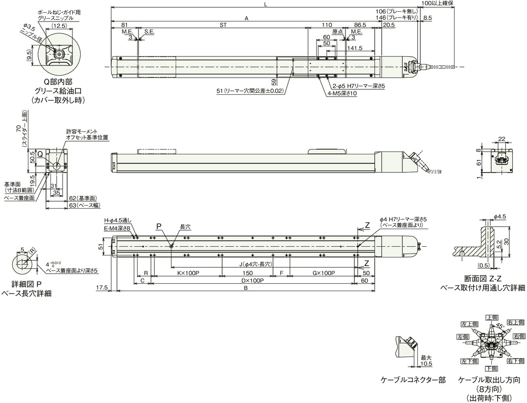
Dimensions
ST: Stroke
ME: Mechanical end
SE: Stroke end
(Note) When performing origin return, the slider will move to the ME, so please be careful not to interfere with the surroundings.
(Note) For details on precautions for changing the cable exit direction, refer to page
Stroke dimensions
stroke
500
550
600
650
700
750
800
850
900
950
1000
1050
1100
1150
1200
1250
1300
1350
1400
1450
1500
L
No brakes
912.5
962.5
1012.5
1062.5
1112.5
1162.5
1212.5
1262.5
1312.5
1362.5
1412.5
1462.5
1512.5
1562.5
1612.5
1662.5
1712.5
1762.5
1812.5
1862.5
1912.5
With brake
952.5
1002.5
1052.5
1102.5
1152.5
1202.5
1252.5
1302.5
1352.5
1402.5
1452.5
1502.5
1552.5
1602.5
1652.5
1702.5
1752.5
1802.5
1852.5
1902.5
1952.5
A
798
848
898
948
998
1048
1098
1148
1198
1248
1298
1348
1398
1448
1498
1548
1598
1648
1698
1748
1798
B
760
810
860
910
960
1010
1060
1110
1160
1210
1260
1310
1360
1410
1460
1510
1560
1610
1660
1710
1760
C
50
0
50
0
50
0
50
0
50
0
50
0
50
0
50
0
50
0
50
0
50
D
6
7
7
8
8
9
9
10
10
11
11
12
12
13
13
14
14
15
15
16
16
E
16
16
18
18
20
20
22
22
24
24
26
26
28
28
30
30
32
32
34
34
36
F
50
0
0
50
50
0
0
50
50
0
0
50
50
0
0
50
50
0
0
50
50
G
2
3
3
3
3
4
4
4
4
5
5
5
5
6
6
6
6
7
7
7
7
H
16
16
16
18
20
20
20
22
24
24
24
26
28
28
28
30
32
32
32
34
36
J
550
600
650
700
750
800
850
900
950
1000
1050
1100
1150
1200
1250
1300
1350
1400
1450
1500
1550
K
2
2
3
3
3
3
4
4
4
4
5
5
5
5
6
6
6
6
7
7
7
R
50
50
0
0
50
50
0
0
50
50
0
0
50
50
0
0
50
50
0
0
50
Mass by stroke
stroke
500
550
600
650
700
750
800
850
900
950
1000
1050
1100
1150
1200
1250
1300
1350
1400
1450
1500
Mass
(kg)No brakes
4.8
5.0
5.2
5.5
5.7
5.9
6.1
6.3
6.5
6.7
6.9
7.1
7.4
7.6
7.8
8.0
8.2
8.4
8.6
8.8
9.1
With brake
5.1
5.3
5.5
5.8
6.0
6.2
6.4
6.6
6.8
7.0
7.2
7.5
7.7
7.9
8.1
8.3
8.5
8.7
8.9
9.2
9.4