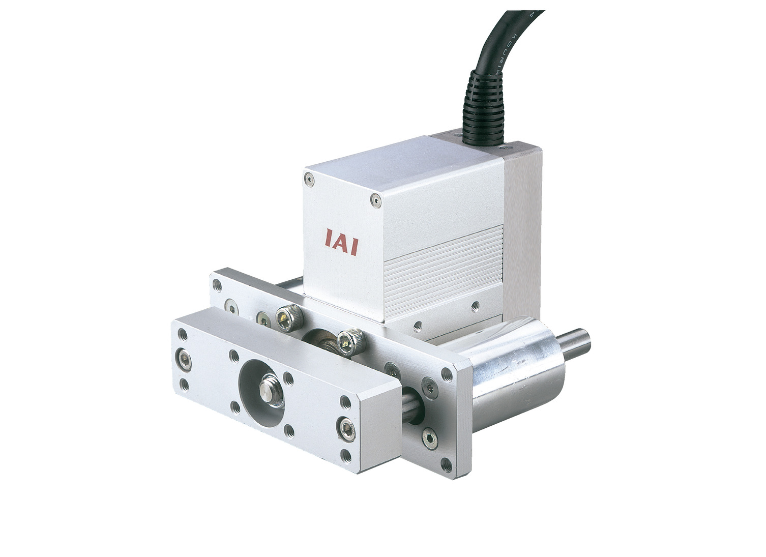
RCA-SRGD4R


Actuator Specification
| Model | Motor power (W) |
Lead (mm) |
Maximum payload capacity | Rated thrust (N) |
Stroke (mm) |
|
|---|---|---|---|---|---|---|
| Level (kg) | Vertical (kg) | |||||
| RCA-SRGD4R-I-20-5-①-②-③-④ | 20 | 5 | 9 | 2 | 41 | 20 to 200 (every 10 mm) (Note 1) |
| RCA-SRGD4R-I-20-2.5-①-②-③-④ | 2.5 | 18 | 5.5 | 81 | ||
Symbol explanation ① Stroke ② Applicable controller ③ Cable length ④ Option
(Note 1) For lengths over 100mm, every 50mm.
| stroke Lead |
20 to 200 (every 10 mm) |
|---|---|
| 5 | 250 |
| 2.5 | 125 |
(Unit: mm/s)
Actuator Specifications
| item | Contents |
|---|---|
| Drive system | Ball screw φ8mm rolled C10 |
| Repeated positioning accuracy | ±0.02mm |
| Lost Motion | Less than 0.1 mm |
| Rod Diameter | φ22mm |
| Rod non-rotation accuracy | ±0.05 degrees |
| Ambient temperature and humidity | 0 to 40°C, 85% RH or less (no condensation) |
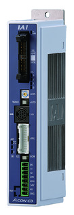
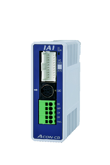
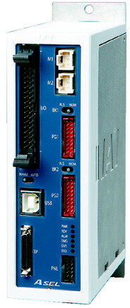
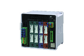
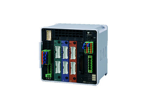
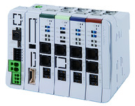
Adaptive Controller
The actuators on this page can be operated with the following controllers. Please select the type that suits your application.
| name | exterior | Maximum number of connectable axes |
Power supply voltage | Control Method | Maximum number of positioning points | ||||||||||||||
|---|---|---|---|---|---|---|---|---|---|---|---|---|---|---|---|---|---|---|---|
| Positioner | Pulse train | program | Network ※Select | ||||||||||||||||
| DV | CC | CIE | PR | CN | ML | ML3 | EC | EP | PRT | SSN | ECM | ||||||||
 |
1 | DC24V | ● ※Select |
● ※Select |
- | ● | ● | ● | ● | ● | ● | ● | ● | ● | ● | - | - | 512 (network specification is 768) |
|
 |
1 | ● ※Select |
● ※Select |
- | - | - | - | - | - | - | - | - | - | - | - | - | 64 | ||
 |
2 | ● | - | ● | ● | ● | - | ● | - | - | - | - | ● | - | - | - | 1500 | ||
 |
8 | - | - | - | ● | ● | ● | ● | ● | - | ● | ● | ● | ● | ● | ● | 256 | ||
 |
6 | - | - | ● | ● | ● | - | ● | ● | - | - | ● | ● | ● | - | - | 256 | ||
 |
16 | - | - | - | ● | ● | ● | ● | - | - | - | ● | ● | ● | - | - | 128 | ||
(Note) For network abbreviations such as DV and CC, please see page
International Standards


Features
Selection considerations
| (1) The payload is the value when operating at an acceleration of 0.3 G (0.2 G for lead 2.5 and vertical use), and is the upper acceleration limit. (2) The usable duty will vary depending on the operating conditions (payload, acceleration/deceleration, etc.). For details, see page . (3) The horizontal payload is when used in conjunction with the external guide. For the usable weight of the included guide alone, see page . (4) Even when used with simple absolute, the encoder type column in the model item will be "I". (5) Caution is required depending on the mounting orientation. For details, see page |
Dimensions
ST: Stroke
ME: Mechanical end
SE: Stroke end
*1 Connects the motor encoder. For cable details, see page
*2 When performing a return to origin, the rod moves to the ME, so please be careful not to interfere with the surroundings.
(Note) The external dimensions remain the same for models with brakes. However, the minimum stroke for models with brakes is 70 mm and cannot be less than 60 mm.
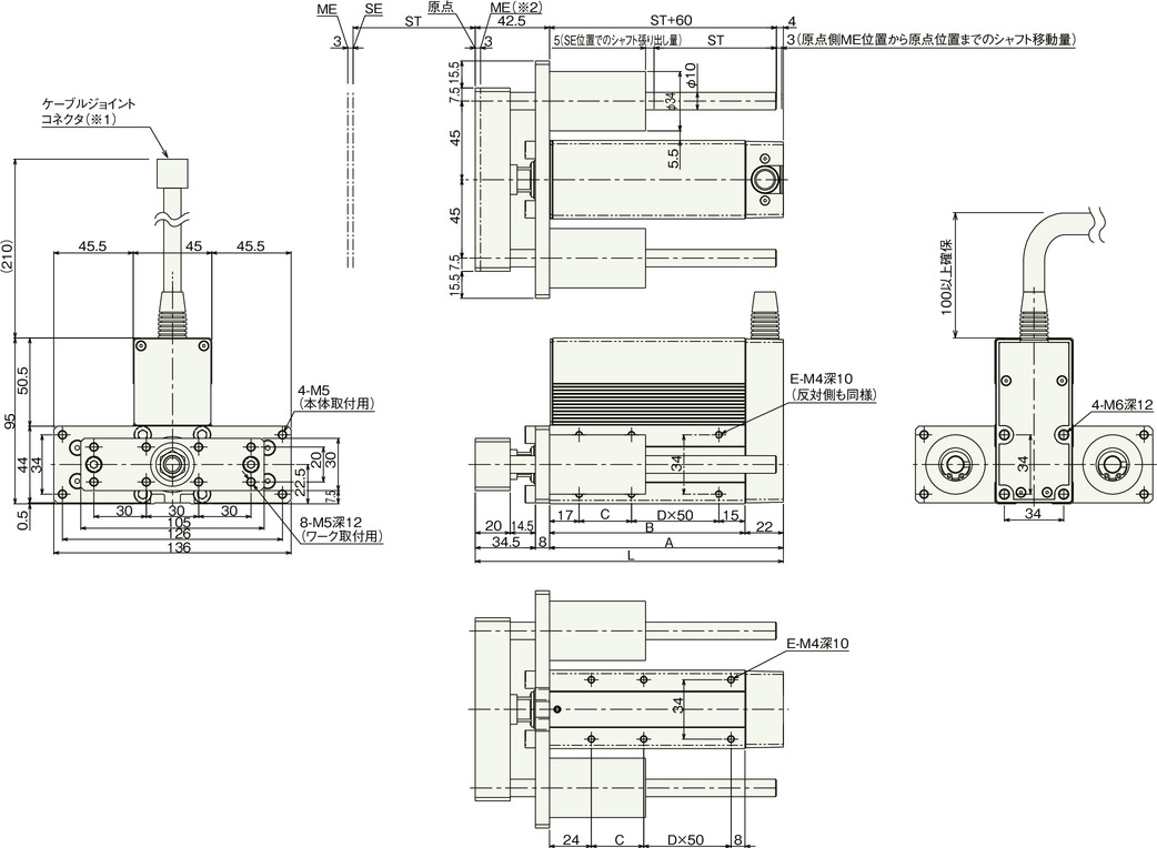
Dimensions and weight by stroke
| stroke | 20 | 30 | 40 | 50 | 60 | 70 | 80 | 90 | 100 | 150 | 200 |
|---|---|---|---|---|---|---|---|---|---|---|---|
| L | 126.5 | 136.5 | 146.5 | 156.5 | 166.5 | 176.5 | 186.5 | 196.5 | 206.5 | 256.5 | 306.5 |
| A | 84 | 94 | 104 | 114 | 124 | 134 | 144 | 154 | 164 | 214 | 264 |
| B | 62 | 72 | 82 | 92 | 102 | 112 | 122 | 132 | 142 | 192 | 242 |
| C | 30 | 40 | 50 | 60 | 70 | 30 | 40 | 50 | 60 | 60 | 60 |
| D | 0 | 0 | 0 | 0 | 0 | 1 | 1 | 1 | 1 | 2 | 3 |
| E | 4 | 4 | 4 | 4 | 4 | 6 | 6 | 6 | 6 | 8 | 10 |
| Mass (kg) | 1.42 | 1.49 | 1.56 | 1.64 | 1.71 | 1.79 | 1.86 | 1.94 | 2.01 | 2.38 | 2.75 |
(Note) With brake, the weight increases by 0.2 kg.