NS-LXMXSA


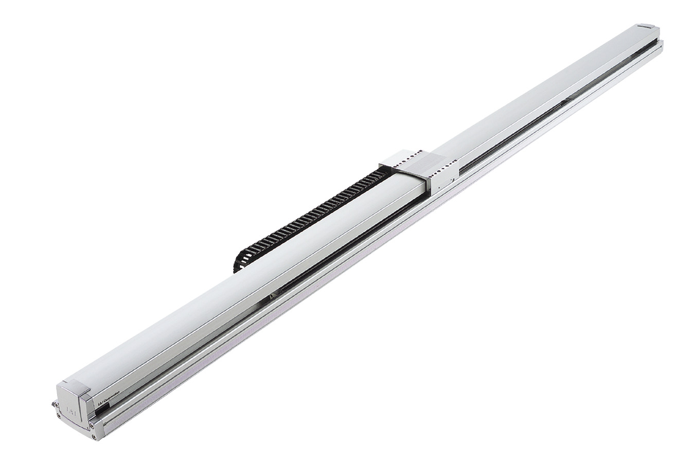
Main Specifications
| item | Contents | |||
|---|---|---|---|---|
| Lead | Ball screw lead (mm) | 40 | 20 | |
| Horizontal | Payload capacity | Maximum payload (kg) | 40 | 80 |
| Speed/Acceleration | Maximum speed (mm/s) | 2400 | 1300 | |
| Rated acceleration/deceleration (G) | 0.3 | 0.3 | ||
| Maximum acceleration/deceleration (G) | 0.3 | 0.3 | ||
| vertical | Payload capacity | Maximum payload (kg) | - | - |
| Speed/Acceleration | Maximum speed (mm/s) | - | - | |
| Rated acceleration/deceleration (G) | - | - | ||
| Maximum acceleration/deceleration (G) | - | - | ||
| Thrust | Rated thrust (N) | 170.0 | 340.1 | |
| brake | Brake specifications | - | - | |
| Brake holding force (kgf) | - | - | ||
| stroke | Minimum stroke (mm) | 2300 | 2300 | |
| Maximum stroke (mm) | 3000 | 3000 | ||
| Stroke pitch (mm) | 100 | 100 | ||
| item | Contents |
|---|---|
| Drive system | Ball screw φ20mm equivalent to rolled C5 |
| Repeated positioning accuracy | ±0.01mm |
| Lost Motion | Less than 0.02 mm |
| base | Material: Aluminum, white anodized |
| Linear guide | Direct-acting infinite circulation type |
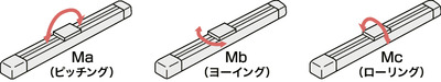
| Static allowable moment | Ma: 374N・m |
| Mb: 533N・m | |
| Mc: 884N・m | |
| Dynamic allowable moment (Note 3) |
Ma: 123N・m |
| Mb: 176N・m | |
| Mc: 291N・m | |
| Ambient temperature and humidity | 0 to 40°C, 85% RH or less (no condensation) |
| Protection rating | - |
| Vibration and shock resistance | 4.9m/ s2 |
| Overseas compatible standards | CE mark, RoHS directive |
| Motor Type | AC servo motor |
| Encoder Type | Incremental/Absolute |
| Encoder Pulse Number | 16384 pulses/rev |
| deadline | Listed on the website [Delivery Date Inquiry] |
(Note 3) Based on a standard rated life of 10,000 km. Operational life may vary depending on operating conditions and installation conditions.
Slider type moment direction
Payload table by speed/acceleration
The unit of payload is kg. Blank spaces mean the item cannot be operated.
| posture | Horizontal | vertical | |||||||||||||||||||||
|---|---|---|---|---|---|---|---|---|---|---|---|---|---|---|---|---|---|---|---|---|---|---|---|
| Lead (mm) |
Maximum speed (mm/s) |
Acceleration (G) | |||||||||||||||||||||
| 0.2 | 0.3 | 0.4 | 0.5 | 0.6 | 0.7 | 0.8 | 0.9 | 1.0 | 1.1 | 1.2 | 0.2 | 0.3 | 0.4 | 0.5 | 0.6 | 0.7 | 0.8 | 0.9 | 1.0 | 1.1 | 1.2 | ||
| 40 | 2400 | 40 | 40 | For horizontal use only. | |||||||||||||||||||
| 20 | 1300 | 80 | 80 | ||||||||||||||||||||
Stroke and maximum speed
(Unit: mm/s)
| stroke Lead |
2300 to 3000 (every 100 mm) |
|---|---|
| 40 | 2400 |
| 20 | 1300 |
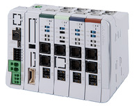
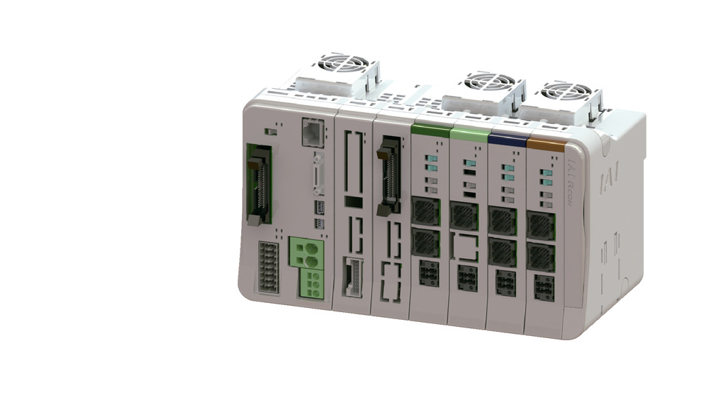
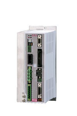
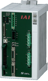
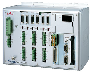
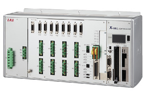
Adaptive Controller
The actuators on this page can be operated with the following controllers. Please select the type that suits your application.
| name | exterior | Maximum number of connectable axes |
Power supply voltage | Control Method | Maximum number of positioning points | ||||||||||||||
|---|---|---|---|---|---|---|---|---|---|---|---|---|---|---|---|---|---|---|---|
| Positioner | Pulse train | program | Network ※Select | ||||||||||||||||
| DV | CC | CIE | PR | CN | ML | ML3 | EC | EP | PRT | SSN | ECM | ||||||||
 |
16 (ML3, SSN, ECM are 8) |
DC24V Single-phase AC200V Three-phase AC200V |
- | - | - | ● | ● | ● | ● | - | - | ● | ● | ● | ● | ● | ● | 128 (ML3, SSN, ECM no position data) |
|
 |
8 | - | - | ● | ● | ● | ● | ● | - | - | - | ● | ● | ● | - | - | 36000 | ||
 |
1 | Single phase AC200V | ● | ● | - | ● | ● | ● | ● | ● | ● | ● | ● | ● | ● | - | ● | 512 (network specification is 768) |
|
 |
2 | Single phase AC 100V/200V |
● | - | ● | ● | ● | - | ● | - | - | - | - | ● | - | - | - | 20000 | |
 |
6 | Single-phase AC200V Three-phase AC200V |
- | - | ● | ● | ● | - | ● | - | - | - | - | ● | - | - | - | 20000 | |
 |
8 | - | - | ● | ● | ● | - | ● | - | - | - | ● | ● | - | - | - | 55000 (varies by type) |
||
(Note) For network abbreviations such as DV and CC, please see page
(Note) Absolute actuators cannot be connected to RCON-SC.
International Standards


Selection considerations
| (1) The "main spec" payload capacity shows the maximum value. For details, please refer to the "Table of payload capacity by speed and acceleration". (2) The "main spec" maximum payload capacity is the value when operated at the maximum speed. (3) The guideline for the overhang load length is 750 mm or less in the Ma, Mb, and Mc directions. |
Dimensions
ST: Stroke
ME: Mechanical end
(Note) The motor cable and encoder cable are connected to the cable joint connector.
For cable details, see page
(Note) When performing origin return, the slider will move to the ME, so please be careful not to interfere with the surroundings.
(Note) The gap between the outer diameter of the cables/hoses stored in the cable carrier and the inner wall, as well as the gap between the cables/hoses themselves, should be 2 mm or more.
(Note) The cables and hoses stored in the cable carrier should have an outer diameter of φ16.8 or less, be arranged horizontally, and not cross each other.
(Note) Please note that if the number of cables/hoses stored in the cable carrier exceeds the above specifications, undue stress will be applied to the cables, significantly shortening their lifespan.
(Note) The cable carrier may expand and become slightly larger than the dimensions.
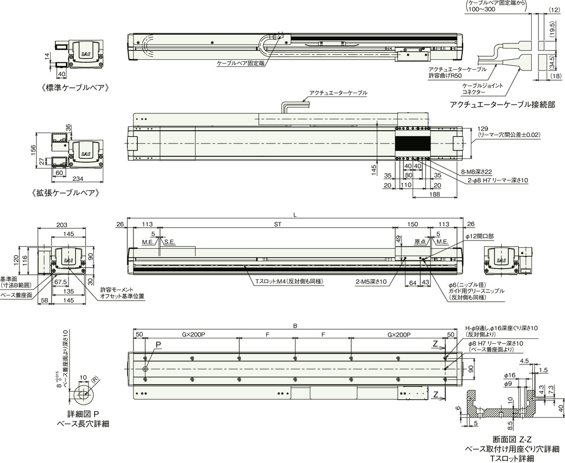
Stroke dimensions
| stroke | 2300 | 2400 | 2500 | 2600 | 2700 | 2800 | 2900 | 3000 |
|---|---|---|---|---|---|---|---|---|
| L | 2728 | 2828 | 2928 | 3028 | 3128 | 3228 | 3328 | 3428 |
| B | 2676 | 2776 | 2876 | 2976 | 3076 | 3176 | 3276 | 3376 |
| F | 288 | 138 | 188 | 238 | 288 | 138 | 188 | 238 |
| G | 5 | 6 | 6 | 6 | 6 | 7 | 7 | 7 |
| H | 26 | 30 | 30 | 30 | 30 | 34 | 34 | 34 |
Mass by stroke
| stroke | 2300 | 2400 | 2500 | 2600 | 2700 | 2800 | 2900 | 3000 |
|---|---|---|---|---|---|---|---|---|
| Mass (kg) | 46.4 | 47.9 | 49.4 | 50.9 | 52.3 | 53.8 | 55.3 | 56.8 |