IXA-4NHN10040


*Note: Some pictures on this page are still Japanese version and the English version pictures are coming soon.
Main Specifications
| item | Contents | ||
|---|---|---|---|
| 4-axis specifications | |||
| Maximum payload (kg) (Note 1) | 50 | ||
| Speed (Note 2) |
Combined maximum speed (mm/s) | 7540 | |
| Maximum speed of each axis | First arm (deg/s) | 280 | |
| Second Arm (deg/s) | 380 | ||
| Vertical axis (mm/s) | 1200 | ||
| Axis of rotation (deg/s) | 920 | ||
| Press (N) (Note 3) | upper limit | 570 | |
| lower limit | 70 | ||
| Arm length (mm) | 1000 | ||
| Arm length of each axis (mm) | First Arm | 600 | |
| Second Arm | 400 | ||
| Each axis motion range | First Arm (degrees) | ±137 | |
| Second Arm (degrees) | ±142 | ||
| Vertical axis (mm) | 400 | ||
| Rotation axis (degrees) | ±360 | ||
| Item | Contents | |
|---|---|---|
| 4-axis specification | ||
| Position repeatability accuracy (Note4) |
In the horizontal plane | ±0.04mm |
| Vertical axis | ±0.02mm | |
| Rotary axis | ±0.01 degrees | |
| User wiring | 10-core (9 cores + shield) AWG24 (rated 30V/MAX 1A) | |
| User piping | Outer diameter φ6, Inner diameter φ4, 3 air tubes (Maximum operating pressure: 0.6 MPa) |
|
| LED Indicator (Note 5) | Amber LED small indicator light, 1 unit, requires DC 24V supply | |
| Brake release switch (Note 6) | Vertical axis fall prevention brake release switch | |
| Tip shaft | Allowable torque | 15N・m |
| Allowable load moment. | 48N・m | |
| Operating ambient temperature and humidity. | 0 to 40°C, 20 to 85% RH or below (without condensation) | |
| Protection rating | IP10 | |
| Vibration resistance and impact resistance | No impact / vibration applied | |
| Noise (Note 7) | below 85dB | |
| International Standards for Compliance. | CE Marking, RoHS Directive | |
| motor capacity | AC Servo Motor | |
| motor capacity | first arm | 1,000W |
| second arm | 750W | |
| Vertical axis | 600W | |
| Rotational axis | 200W | |
| Encoder pulse count | Battery-less Absolute | |
| Encoder pulse count | 131,072 pulse/rev | |
| Delivery time | It is listed on the website under [Delivery Inquiry]. | |
Correlation diagram between pressing force and current limit value (reference value)
This is the pressing force at the tip of the vertical axis. (Note 3)
Adaptive Controller
The actuators on this page can be operated with the following controllers. Please select the type that suits your application.
| name | exterior | Maximum number of connectable axes |
Power supply voltage | Control Method | Maximum number of positioning points | ||||||||||||||
|---|---|---|---|---|---|---|---|---|---|---|---|---|---|---|---|---|---|---|---|
| Positioner | Pulse train | program | Network ※Select | ||||||||||||||||
| DV | CC | CIE | PR | CN | ML | ML3 | EC | EP | PRT | SSN | ECM | ||||||||
 |
4 | Three-phase AC200V | - | - | ● | ● | ● | ● | ● | - | - | - | ● | ● | - | - | - | 36666 | |
(Note) For network abbreviations such as DV and CC, please see page
International Standards


Selection considerations
| (1) For (Note 1) to (Note 8), please refer to page . (2) The maximum setting value for acceleration/deceleration varies depending on the mass of the transported object, the travel distance, and the location. In addition, continuous operation at the maximum setting value may result in an overload error. When performing continuous operation, lower the acceleration/deceleration value, or set a stop time after acceleration/deceleration by referring to the duty ratio (guideline). (3) An absolute reset is required when replacing a motor, etc. An adjustment jig is required to perform an absolute reset on the rotating axis. For details, please refer to page . (4) SCARA robots cannot be operated continuously at 100% speed and acceleration. For the operating conditions, please refer to the "Guideline for Acceleration/Deceleration Settings" page. (5) When switching the arm system, the arm will temporarily extend in a straight line, so please be careful of interference with peripheral devices. |
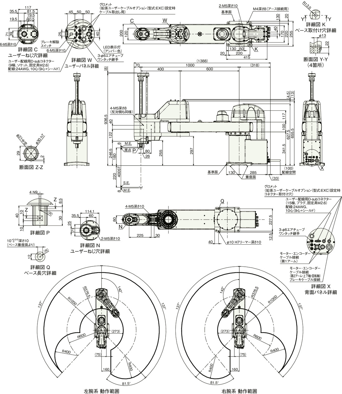
Dimensions
IXA-4NHN10040
ST: Stroke
ME: Mechanical end
SE: Stroke end
(Note) For cable connections, see page
mass
| item | Contents |
|---|---|
| mass | 80.0kg |
Cycle Time
| item | time |
|---|---|
| Standard Cycle Time | 0.56 seconds |
| Continuous Cycle Time | 0.69 seconds |
Standard/continuous cycle time indicates the time required when operating at the fastest round trip operation setting under the conditions below.
2kg transport, vertical movement 25mm, horizontal movement 300mm (coarse positioning arch motion)
[Standard cycle time]
This is the time required for maximum speed operation. Generally, this is a guide to high speed performance.
Please note that continuous operation at maximum speed is not possible.
[Continuous cycle time]
This is the cycle time for continuous operation.
Allowable moment of inertia of tip shaft
| Number of axes | Allowable moment of inertia of tip shaft |
|---|---|
| 4-axis specifications | 0.5 kg m2 |
This is the allowable moment of inertia converted from the center of the tip axis (rotation axis) of a SCARA robot.
The offset from the center of the tip axis to the center of gravity of the tool must be within the following values.
If the tool center of gravity is moved away from the center of the tip of the shaft, the speed and acceleration must be reduced appropriately. The extension length is limited by the load and operating conditions.
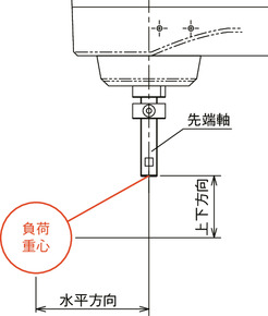
| Horizontal | vertical direction |
|---|---|
| Under 200mm | 150mm or less |
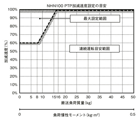
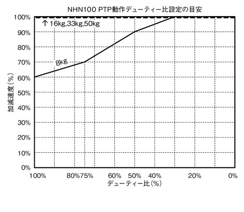
Acceleration/deceleration setting guideline
The SCARA Robot IXA cannot be operated continuously at the maximum acceleration/deceleration and maximum speed in the catalog. When operating at the maximum acceleration/deceleration, set the stop time by referring to the continuous operation duty ratio guideline graph. If continuous operation is required, operate the robot at an acceleration/deceleration setting within the continuous operation guideline range in the acceleration/deceleration setting guideline graph.
(1) For PTP operation, be sure to use the WGHT command in the program to set the mass and moment of inertia before operating. The maximum acceleration/deceleration at which SCARA can operate for each load capacity is 100%. Please note that even with the same acceleration/deceleration and speed settings, the operation time will differ if the load mass is different. The values (%) set for acceleration and deceleration in PTP operation are adjusted by the optimal speed and optimal acceleration/deceleration functions to values at which the speed and acceleration/deceleration can be operated depending on the load mass and movement posture. However, the optimal acceleration/deceleration function does not guarantee that operation is possible with all operation patterns.
(2) Adjust the acceleration/deceleration setting by gradually increasing it from the continuous operation guideline value.
(3) If an overload error occurs, reduce the acceleration/deceleration as appropriate, or adjust the stopping time based on the guideline for the continuous operation duty ratio.
(4) Duty ratio (%) = (operating time / (operating time + stopped time)) x 100
(5) When you want to move the robot horizontally at high speed, try to operate the vertical axis as close to the upper end as possible.
(6) Keep the moment of inertia and payload below the allowable values.
(7) The payload capacity indicates the moment of inertia about the center of the rotation axis and the mass.
(8) When operating the robot, observe the appropriate acceleration and deceleration according to the mass and moment of inertia. Failure to do so may result in premature end of life, damage or vibration of the drive parts.
(9) If the load has a large moment of inertia, vibration may occur in the vertical axis depending on the position of the vertical axis. If vibration occurs, reduce the acceleration/deceleration as appropriate.
PTP Operation
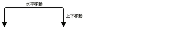
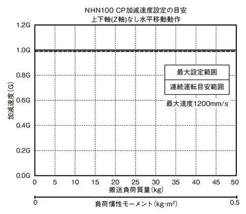
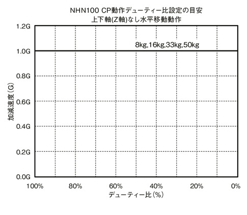
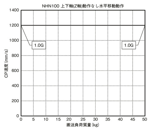
CP operation
Horizontal
Up and down
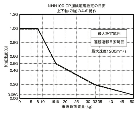
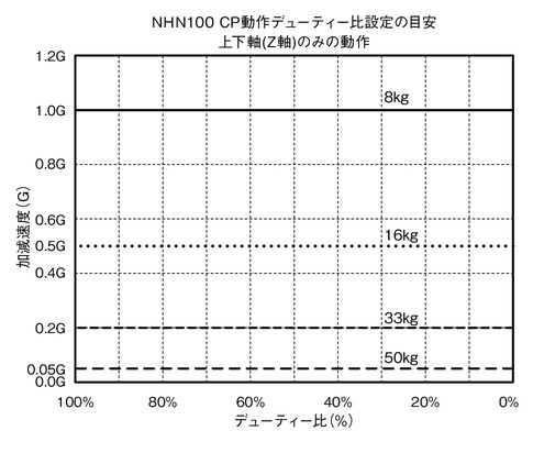
CP operation speed/acceleration/deceleration limit
Horizontal
Up and down