IX-NNN1805

*Note: Some pictures on this page are still Japanese version and the English version pictures are coming soon.
Model Specifications
| Model | Shaft Configuration | Arm length (mm) |
Motor capacity (W) |
Operating range | Repeated positioning accuracy (mm) (Note 1) |
Maximum operating speed during PTP operation (Note 2) |
Standard cycle time (s) (Note 3) |
Payload capacity (kg) (Note 4) |
3rd axis (vertical axis) pressing force control range (N) |
4th axis allowable load |
||||
|---|---|---|---|---|---|---|---|---|---|---|---|---|---|---|
| Rating | maximum | Upper limit (Note 5) |
Lower limit (Note 5) |
Allowable moment of inertia (kg m2 ) (Note 6) |
Allowable torque (N・m) |
|||||||||
| IX-NNN1805-①-T2-② | 1 axis | First Arm | 105 | 12 | ±125 degrees | ±0.01 (XY) |
2555mm/s (composite speed) |
0.38 | 0.2 | 1.0 | 14.7 | 9.8 | 0.000386 | 0.13 |
| 2-axis | Second Arm | 75 | 12 | ±145 degrees | ||||||||||
| 3-axis | Vertical axis | - | 12 | 50mm | ±0.010 | 720mm/s | ||||||||
| 4th axis | Rotation axis | - | 60 | ±360 degrees | ±0.005 | 1800 degrees/s | ||||||||
Symbol Explanation ① Cable length ② Option
Actuator Specifications
| item | Contents |
|---|---|
| Encoder Type | Absolute |
| User wiring | 8-core AWG26 shielded Connector: SMP-08V-NC (JST) |
| User piping | 2 air tubes with outer diameter of φ3 and inner diameter of φ2 (normal operating pressure 0.7MPa) |
| Alarm indicator (Note 7) | 1 small red LED indicator light (24V DC supply required) |
| Ambient temperature and humidity | Temperature: 0 to 40°C Humidity: 20 to 85% RH or less (no condensation) |
| Body weight | 3.0kg |
| Cable length (Note 9) | 3L: 3m (standard) 5L: 5m |
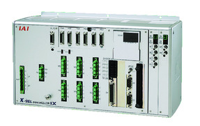
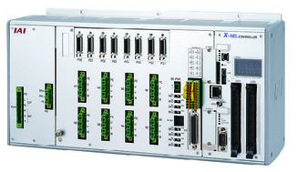
Adaptive Controller
The actuators on this page can be operated with the following controllers. Please select the type that suits your application.
| name | exterior | Maximum number of connectable axes |
Power supply voltage | Control Method | Maximum number of positioning points | ||||||||||||||
|---|---|---|---|---|---|---|---|---|---|---|---|---|---|---|---|---|---|---|---|
| Positioner | Pulse train | program | Network ※Select | ||||||||||||||||
| DV | CC | CIE | PR | CN | ML | ML3 | EC | EP | PRT | SSN | ECM | ||||||||
 |
6 | Three-phase AC200V | - | - | ● | ● | ● | - | ● | - | - | - | - | ● | - | - | - | 20000 | |
 |
8 | - | - | ● | ● | ● | - | ● | - | - | - | ● | ● | - | - | - | 36666 (varies by type) |
||
(Note) For network abbreviations such as DV and CC, please see page
(Note) Up to a maximum of SCARA + 4-axis robots can be controlled.
(Note) When connecting two SCARA robots, please select XSEL-RAXD/SAXD. However, some combinations of SCARA robots may not be possible to connect. Please check page
International Standards


(Note) CE is optional.
Selection considerations
| (1) For (Notes 1) to (Notes 10), refer to page . (2) SCARA robots cannot be operated continuously at 100% speed and acceleration. For operating conditions, refer to the technical information on page . (3) If the absolute data in the encoder is lost and an absolute reset is required, an adjustment jig is required. For details, refer to page . (4) Flange options are available. For details, refer to page |
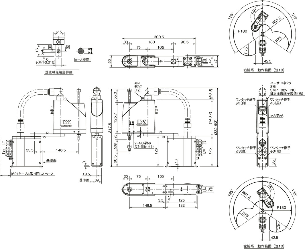
Dimensions
*1 2-M3 depth 6 penetrates the arm. If the mounting screw is too long, it may interfere with the internal mechanism, so please be careful.
*2 The ALM indicator will light up when the customer takes the signal from the I/O output of the controller and applies DC24V to the LED terminal in the user wiring.
*3 The height dimension varies depending on the actuator posture in the specified position. The maximum guideline value is stated.