ICSPA2-B2NA□M
Maximum speed by stroke
(Unit: mm/s)
| 200 to 700 | 2250-3000 | |
|---|---|---|
| X-Axis | - | 1300 |
| Y-Axis | 1200 | - |
Payload by acceleration
The units in the table are kg.
| Y-axis stroke | |||||||
|---|---|---|---|---|---|---|---|
| 200 | 300 | 400 | 500 | 600 | 700 | ||
|
acceleration |
0.3 | 40.0 | 40.0 | 33.0 | 27.3 | 22.9 | 19.3 |
| 0.4 | 30.0 | 30.0 | 30.0 | 27.3 | 22.9 | 19.3 | |
| 0.5 | 21.6 | 21.6 | 21.6 | 21.6 | 21.6 | 19.3 | |
| 0.6 | 18.0 | 18.0 | 18.0 | 18.0 | 17.5 | 16.6 | |
| 0.7 | 15.3 | 14.9 | 14.0 | 13.0 | 12.1 | 11.2 | |
| 0.8 | 12.2 | 11.3 | 10.4 | 9.4 | 8.5 | 7.6 | |
| 0.9 | 9.5 | 8.6 | 7.7 | 6.7 | 5.8 | 4.9 | |
| 1.0 | 6.8 | 5.9 | 5.0 | - | - | - | |
Adaptive Controller
Please refer to the page for each controller. ( Page
International Standards

Selection considerations
| (1) The stroke column in the model number is expressed in cm (centimeters). (2) The cable length is the length from the X-axis connector box (or from the X-axis actuator cable in the case of a cable bearer specification) to the controller. The standard is 3m or 5m, but other lengths are also available in meters. Up to 20m is possible. (3) The rated acceleration is 0.3G. The Y-axis can operate up to a maximum of 1G, but the upper limit for the X-axis is 0.3G. |
Dimensions
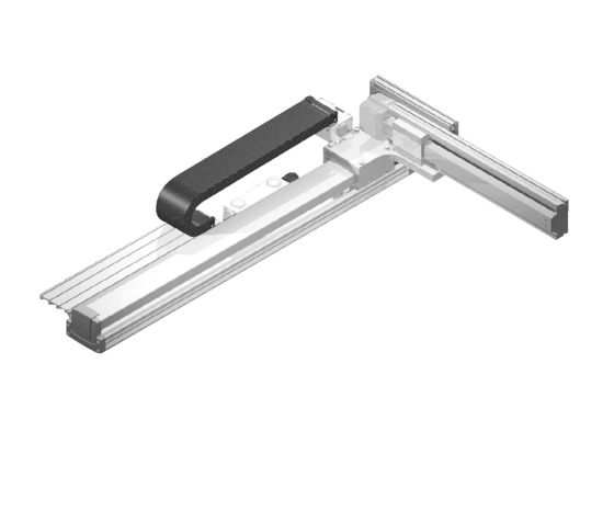
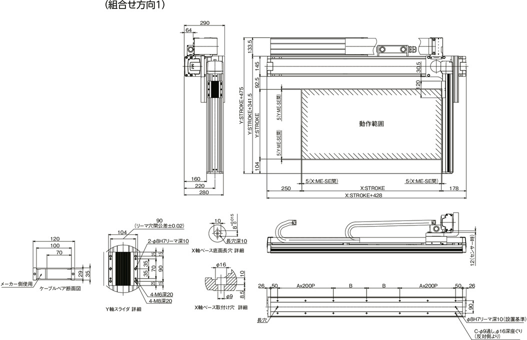
ICSPA2-B2NA□M-CT (Cableveyor specification) Assembly direction 1
ME: Mechanical End
SE: Stroke end
(Note) The combination position on the drawing is the origin position. If you want to change the origin position, please specify the option NM. Please note that if you want to change the origin position after delivery, you will need to return the product for adjustment.
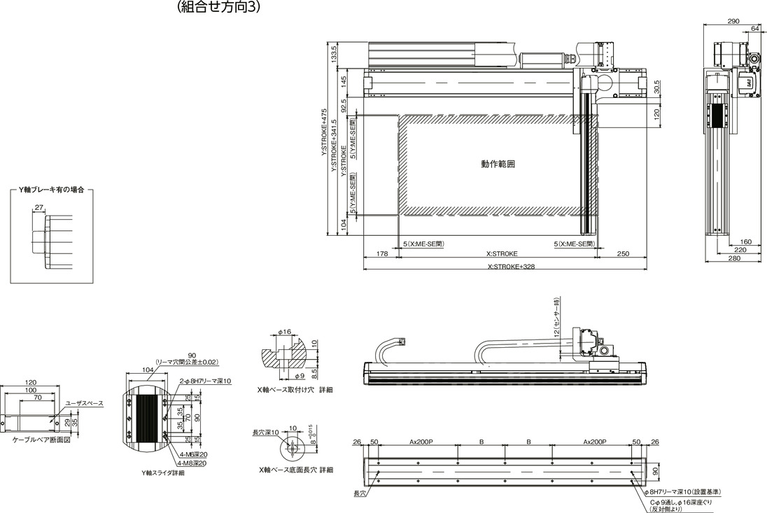
ICSPA2-B2NA□M-CT (Cableveyor specification) Combination direction 3
(Note) The combination position on the drawing is the origin position. If you want to change the origin position, please specify the option NM. Please note that if you want to change the origin position after delivery, you will need to return the product for adjustment.
| X-Stroke | 2250 | 2300 | 2350 | 2400 | 2450 | 2500 | 2550 | 2600 | 2650 | 2700 | 2750 | 2800 | 2850 | 2900 | 2950 | 3000 |
|---|---|---|---|---|---|---|---|---|---|---|---|---|---|---|---|---|
| A | 5 | 5 | 5 | 6 | 6 | 6 | 6 | 6 | 6 | 6 | 6 | 7 | 7 | 7 | 7 | 7 |
| B | 263 | 288 | 313 | 138 | 163 | 188 | 213 | 238 | 263 | 288 | 313 | 138 | 163 | 188 | 213 | 238 |
| C | 26 | 26 | 26 | 30 | 30 | 30 | 30 | 30 | 30 | 30 | 30 | 34 | 34 | 34 | 34 | 34 |
Common Specifications
| Drive system | Ball screw rolled C5 equivalent |
| Repeated positioning accuracy | ±0.01mm |
| Lost Motion | Less than 0.02 mm |
| guide | Base integrated type |
| base | Material: Aluminum, white anodized |
| X-axis motor output/lead | 400W/20mm |
| Y-axis motor output/lead | 200W/20mm |
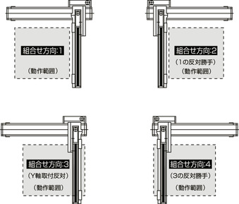
XY combination direction
Model details
| XY combination direction (Note 1) |
Model | ||
|---|---|---|---|
| 1 | ICSPA2-B2NA1M-①-②③-④⑤-T2-⑥-⑦ | ||
| 2 | ICSPA2-B2NA2M-①-②③-④⑤-T2-⑥-⑦ | ||
| 3 | ICSPA2-B2NA3M-①-②③-④⑤-T2-⑥-⑦ | ||
| 4 | ICSPA2-B2NA4M-①-②③-④⑤-T2-⑥-⑦ | ||
(Note 1) For the XY assembly direction, see the diagram below. For the contents of ① to ⑦ in the above model numbers, see the table below.
Model code explanation
| number | Contents | Notation |
|---|---|---|
| ① | Encoder Type | A: Absolute I: Incremental |
| ② | X-axis stroke | 225: 2250mm ~ 300: 3000mm |
| ③ | X-Axis Options | See option table |
| ④ | Y-axis stroke | 20: 200mm ~ 70: 700mm |
| ⑤ | Y-Axis Options | See option table |
| ⑥ | Cable length | 3L: 3m 5L: 5m □L: □m |
| ⑦ | Y-axis cable wiring (Note 2) | CT: Cable bear |
(Note 2) For cable bear dimensions, refer to
Configuration axis
| Axis Name | Model | Reference page |
|---|---|---|
| X-Axis | NS-LXMXSA-①-400-20-②-T2-③-⑧ | |
| Y-Axis | ISPA-MYM-①-200-20-②-T2-⑤ | - |
(Note) For ① to ⑤ in the above model numbers, please refer to the symbols in the model numbers above.
(Note) The following symbols will be entered in ⑧ in the above model numbers.
NT1: In the case of orthogonal combination directions 1 and 3
NT2: In the case of orthogonal combination directions 2 and 4
(Note) Although a cable bearer is installed on the nut rotating type/large linear robot even with a single axis, when it is assembled into a Cartesian robot, a different cable bearer is used, so the single axis will have a specification without a cable bearer (NT1 or NT2).