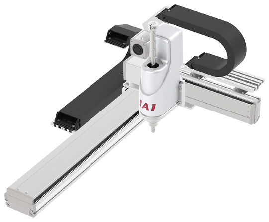
ICSB4-BE□HZRM
ICSPB4-BE□HZRM
Product Features


Maximum speed by stroke
(Unit: mm/s)
| stroke | ||||||||
|---|---|---|---|---|---|---|---|---|
| 200 | 300-700 | 750-800 | 850-900 | 950-1000 | 1050~1100 | 1150~1200 | 1250-1300 | |
| X-Axis | - | 1200 | 920 | 765 | 645 | 550 | 440 | |
| Y-Axis | 1200 | - | ||||||
(Unit: mm/s)
| Stroke 200mm | |
|---|---|
| Z-axis | 1256mm/s (Note) |
(Unit: mm/s)
| Stroke ±360 degrees | |
|---|---|
| Rotation axis | 2200 degrees/s (Note) |
(Note) This is the value when operated with a PTP operation command.
Payload capacity
The units in the table are kg.
| Y-axis stroke | |||||||
|---|---|---|---|---|---|---|---|
| 200 | 300 | 400 | 500 | 600 | 700 | ||
| Z-axis stroke | 200 | Rated 2.0kg (acceleration/deceleration 0.3G) Maximum 6.0kg (acceleration/deceleration 0.1G) |
|||||
(Note) This is the value when operating at the rated acceleration. Please refer to "Notes on selection."
Adaptive Controller
Please refer to the page for each controller. ( Page
International Standards

Selection considerations
| (1) The stroke column of the model number is written in cm (centimeters). (2) The cable length is the length from the X-axis connector box (from the X-axis actuator cable in the case of a cable bearer specification) to the controller. The standard length is 3m or 5m, but other lengths are also available in meters. Up to 20m is possible. (3) The rated acceleration is 0.3G. The payload decreases as the acceleration increases. (4) Please note that the maximum speed decreases as the stroke increases. Also, if moving with the vertical axis lowered, reduce the speed and acceleration. (5) The values in [ ] are for high-precision model types. (6) If absolute data is lost, an absolute reset must be performed. An adjustment jig (model number: JG-ZRM) is required for absolute reset. (Not included with the main unit) |
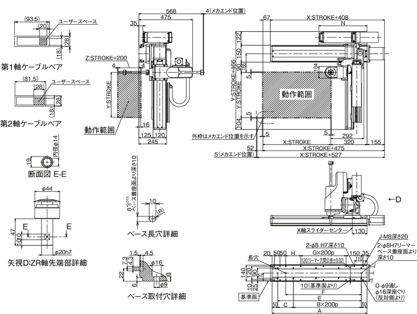
Dimensions
ICSB4 [ICSPB4] -BE HZRM-CT-CT (Cableveyor specification) Combination direction 1
(Note) The combination position on the drawing is the origin position. If you want to change the origin position, please specify the option NM.
Please note that if you change the origin position after delivery, a return adjustment is required.
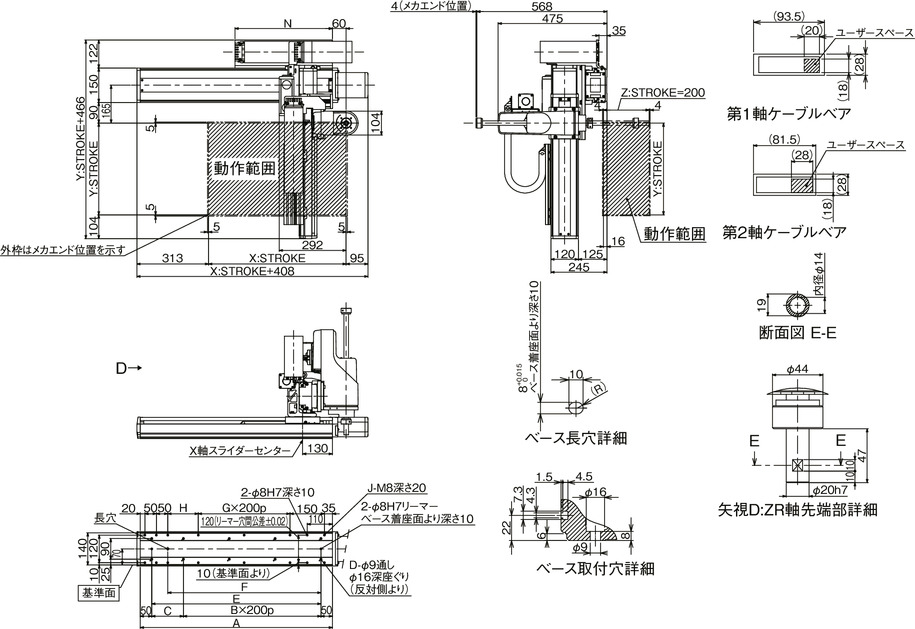
ICSB4 [ICSPB4] -BE□HZRM-CT-CT (Cableveyor specification) Combination direction 3
(Note) The combination position on the drawing is the origin position. If you want to change the origin position, please specify the option NM.
Please note that if you change the origin position after delivery, a return adjustment is required.
| X-axis stroke | 300 | 350 | 400 | 450 | 500 | 550 | 600 | 650 | 700 | 750 | 800 | 850 | 900 | 950 | 1000 | 1050 | 1100 | 1150 | 1200 | 1250 | 1300 |
|---|---|---|---|---|---|---|---|---|---|---|---|---|---|---|---|---|---|---|---|---|---|
| A | 538 | 588 | 638 | 688 | 738 | 788 | 838 | 888 | 938 | 988 | 1038 | 1088 | 1138 | 1188 | 1238 | 1288 | 1338 | 1388 | 1438 | 1488 | 1538 |
| B | 1 | 1 | 2 | 2 | 2 | 2 | 3 | 3 | 3 | 3 | 4 | 4 | 4 | 4 | 5 | 5 | 5 | 5 | 6 | 6 | 6 |
| C | 238 | 288 | 138 | 188 | 238 | 288 | 138 | 188 | 238 | 288 | 138 | 188 | 238 | 288 | 138 | 188 | 238 | 288 | 138 | 188 | 238 |
| D | 6 | 6 | 8 | 8 | 8 | 8 | 10 | 10 | 10 | 10 | 12 | 12 | 12 | 12 | 14 | 14 | 14 | 14 | 16 | 16 | 16 |
| E | 438 | 488 | 538 | 588 | 638 | 688 | 738 | 788 | 838 | 888 | 938 | 988 | 1038 | 1088 | 1138 | 1188 | 1238 | 1288 | 1338 | 1388 | 1438 |
| F | 368 | 418 | 468 | 518 | 568 | 618 | 668 | 718 | 768 | 818 | 868 | 918 | 968 | 1018 | 1068 | 1118 | 1168 | 1218 | 1268 | 1318 | 1368 |
| G | 0 | 0 | 1 | 1 | 1 | 1 | 2 | 2 | 2 | 2 | 3 | 3 | 3 | 3 | 4 | 4 | 4 | 4 | 5 | 5 | 5 |
| H | 233 | 283 | 133 | 183 | 233 | 283 | 133 | 183 | 233 | 283 | 133 | 183 | 233 | 283 | 133 | 183 | 233 | 283 | 133 | 183 | 233 |
| J | 10 | 10 | 12 | 12 | 12 | 12 | 14 | 14 | 14 | 14 | 16 | 16 | 16 | 16 | 18 | 18 | 18 | 18 | 20 | 20 | 20 |
| N | 275 | 300 | 325 | 350 | 375 | 400 | 425 | 450 | 475 | 500 | 525 | 550 | 575 | 600 | 625 | 650 | 675 | 700 | 725 | 750 | 775 |
Common Specifications
| X-Axis | Y-Axis | Z-axis | Rotation axis | |
|---|---|---|---|---|
| Drive system | Ball screw rolled C10 [equivalent to rolled C5] | Belt + ball screw spline | Belt + gear reducer + spline | |
| Repeated positioning accuracy | ±0.01mm【±0.005mm】 | ±0.01mm | ±0.005° | |
| Lost Motion | 0.05mm or less [0.02mm or less] | - | ||
| guide | Base integrated type | - | ||
| base | Material: Aluminum, white anodized | - | ||
| Motor Power/Lead | 400W/20mm | 200W/20mm | 200W/20mm | 200W/- |
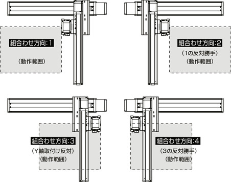
XY combination direction
Model details
| XY combination direction (Note 1) |
Model | ||
|---|---|---|---|
| 1 | ICSB4 [ICSPB4]-BE1HZRM-WA-①②-③④-⑤⑥-⑦⑧-T□-⑨-⑩ | ||
| 2 | ICSB4 [ICSPB4]-BE2HZRM-WA-①②-③④-⑤⑥-⑦⑧-T□-⑨-⑩ | ||
| 3 | ICSB4 [ICSPB4]-BE3HZRM-WA-①②-③④-⑤⑥-⑦⑧-T□-⑨-⑩ | ||
| 4 | ICSB4 [ICSPB4]-BE4HZRM-WA-①②-③④-⑤⑥-⑦⑧-T□-⑨-⑩ | ||
(Note 1) For the XY combination direction, see the diagram below. For the contents of ① to ⑩ in the above model numbers, see the table below.
Model code explanation
| number | Contents | Notation |
|---|---|---|
| ① | X-axis stroke | 30: 300mm ~ 130: 1300mm |
| ② | X-Axis Options | See option table |
| ③ | Y-axis stroke | 20: 200mm ~ 70: 700mm |
| ④ | Y-Axis Options | See option table |
| ⑤ | Z-axis stroke | 20: 200mm |
| ⑥ | Z-Axis Options | See option table |
| ⑦ | Rotation axis operating range | 36: 360 degrees |
| ⑧ | Rotation Axis Options | See option table |
| ⑨ | Cable length | 3L: 3m 5L: 5m □L: Length specification |
| ⑩ | Y-axis to Z-axis cable routing | CT-CT: Cable bear - Cable bear |
Configuration axis
| Axis Name | Model | Reference page |
|---|---|---|
| X-Axis | ISB [ISPB]-LXM-WA-400-20-①-T2-⑪-② | |
| Y-Axis | ISB [ISPB]-MXM-WA-200-20-③-T2-⑪-④ | |
| Z-axis/Rotation axis | ZR-M-WA-200-20-200-T2-⑥ |
(Note) For the above model numbers ① to ⑥, please refer to the symbols in the model numbers in the table above. Note that the stroke is expressed in mm (millimeters).
(Note) ⑪ in the above model numbers indicates the cable exit direction. For the cable exit direction, refer to page