ICSPB2-BQ□M
ICSPB2-BQ□M
Product Features


Maximum speed by stroke
(Unit: mm/s)
| 100 to 700 | 900-3000 | |
|---|---|---|
| X-Axis | - | 1250 |
| Y-Axis | 1200 | - |
Payload by acceleration
The units in the table are kg.
| Y-axis stroke | ||||||||||||||
|---|---|---|---|---|---|---|---|---|---|---|---|---|---|---|
| 100 | 150 | 200 | 250 | 300 | 350 | 400 | 450 | 500 | 550 | 600 | 650 | 700 | ||
| Acceleration (Note 3) | 0.2 | 65.0 | 65.0 | 65.0 | 65.0 | 62.3 | 55.9 | 50.7 | 46.1 | 42.0 | 38.4 | 35.2 | 32.2 | 29.6 |
| 0.3 | 65.0 | 65.0 | 65.0 | 65.0 | 62.3 | 55.9 | 50.7 | 46.1 | 42.0 | 38.4 | 35.2 | 32.2 | 29.6 | |
| 0.4 | 64.5 | 63.7 | 62.9 | 62.1 | 59.9 | 54.1 | 49.8 | 44.8 | 40.9 | 37.4 | 34.3 | 31.5 | 28.9 | |
| 0.5 | 47.4 | 46.6 | 45.8 | 45.0 | 44.3 | 43.5 | 42.8 | 40.4 | 36.5 | 33.0 | 29.9 | 27.0 | 24.5 | |
| 0.6 | 36.6 | 35.8 | 35.0 | 34.2 | 33.5 | 32.7 | 31.9 | 31.1 | 27.8 | 24.8 | 22.2 | 19.8 | 17.6 | |
| 0.7 | 29.4 | 28.6 | 27.8 | 27.0 | 26.3 | 25.5 | 24.8 | 23.9 | 21.6 | 19.0 | 16.7 | 14.6 | 12.7 | |
| 0.8 | 23.1 | 22.3 | 21.5 | 20.7 | 20.0 | 19.2 | 18.4 | 17.6 | 16.8 | 14.7 | 12.6 | 10.7 | 9.0 | |
| 0.9 | 18.6 | 17.8 | 17.0 | 16.2 | 15.5 | 14.7 | 13.9 | 13.1 | 12.3 | 11.3 | 9.4 | 7.7 | 6.1 | |
| 1 | 15.0 | 14.2 | 13.4 | 12.6 | 11.9 | 11.1 | 10.3 | 9.5 | 8.7 | 7.9 | 6.9 | 5.2 | 3.8 | |
| 1.1 | 9.6 | 8.8 | 8.0 | 7.2 | 6.5 | 5.7 | 5.0 | 4.1 | 3.3 | 2.5 | 1.8 | 1.0 | - | |
| 1.2 | 4.2 | 3.4 | 2.6 | 1.8 | 1.1 | - | - | - | - | - | - | - | - | |
(Note 3) The payload is when both the X-axis and Y-axis are operated at the acceleration shown in the table.
Adaptive Controller
Please refer to the page for each controller. ( Page
International Standards

Selection considerations
| (1) The stroke column in the model number is written in cm (centimeters). (2) The cable length is the length from the X-axis connector box (or from the X-axis actuator cable in the case of a cable bearer specification) to the controller. The standard length is 3m or 5m, but other lengths are also available in meters. Up to 20m is possible. (3) Please note that the maximum speed decreases as the stroke becomes longer. (4) The rated acceleration is 0.3G for the X-axis and 0.4G for the Y-axis. The payload decreases when the acceleration is increased. (5) The figures in brackets [ ] are for high-precision model. |
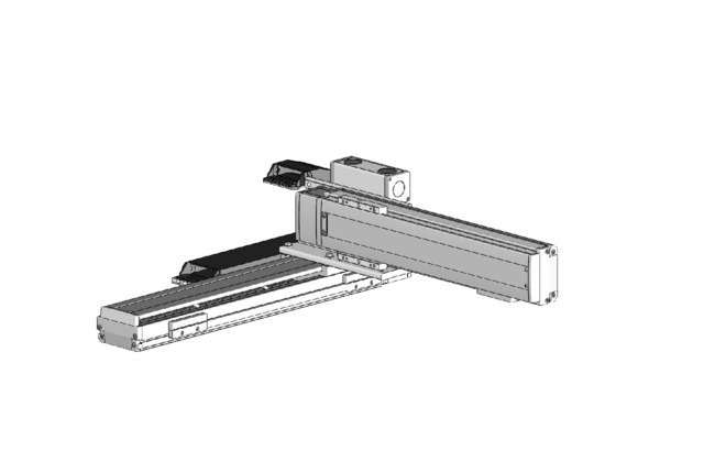
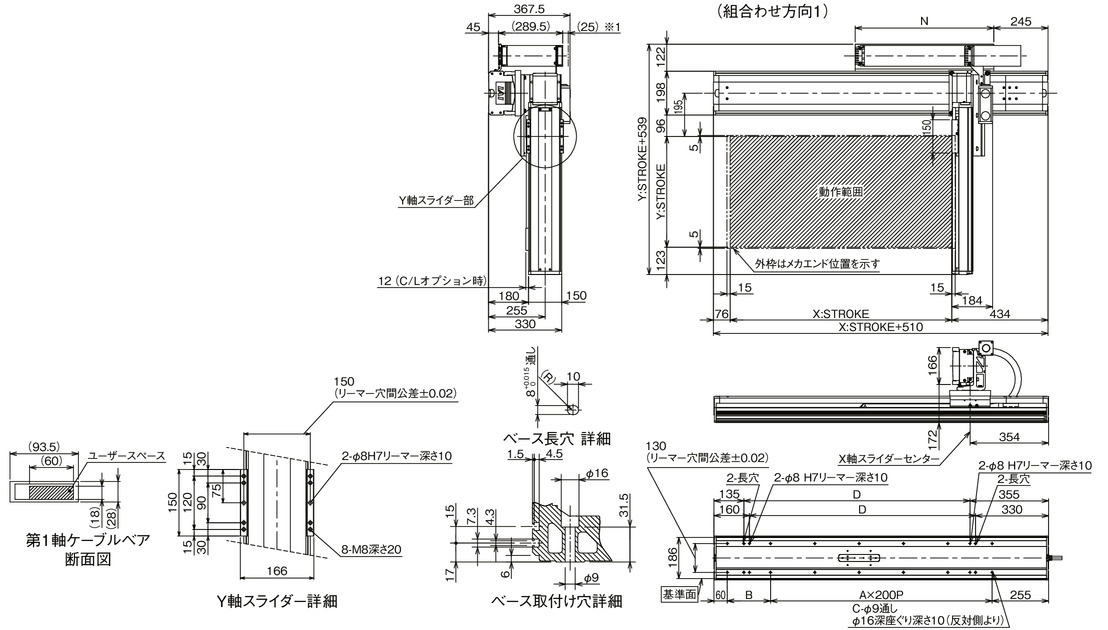
Dimensions
ICSB2 [ICSPB2] -BQ M-CT (Cableveyor specification) Combination direction 1
*1 The cable carrier may expand up to 25 mm upwards.
(Note) The combination position on the drawing is the origin position. If you want to change the origin position, please specify the option NM. Please note that if you want to change the origin position after delivery, you will need to return the product for adjustment.
English version is coming soon!
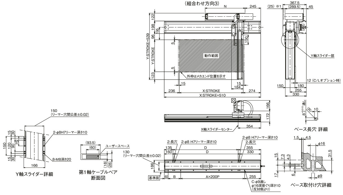
ICSB2 [ICSPB2] -BQ M-CT (Cableveyor specification) Combination direction 3
*1 The cable carrier may expand up to 25 mm upwards.
(Note) The combination position on the drawing is the origin position. If you want to change the origin position, please specify the option NM. Please note that if you want to change the origin position after delivery, you will need to return the product for adjustment.
English version is coming soon!
| X-axis stroke | 900 | 1000 | 1100 | 1200 | 1300 | 1400 | 1500 | 1600 | 1700 | 1800 | 1900 | 2000 | 2100 | 2200 | 2300 | 2400 | 2500 | 2600 | 2700 | 2800 | 2900 | 3000 |
|---|---|---|---|---|---|---|---|---|---|---|---|---|---|---|---|---|---|---|---|---|---|---|
| A | 4 | 5 | 5 | 6 | 6 | 7 | 7 | 8 | 8 | 9 | 9 | 10 | 10 | 11 | 11 | 12 | 12 | 13 | 13 | 14 | 14 | 15 |
| B | 295 | 195 | 295 | 195 | 295 | 195 | 295 | 195 | 295 | 195 | 295 | 195 | 295 | 195 | 295 | 195 | 295 | 195 | 295 | 195 | 295 | 195 |
| C | 12 | 14 | 14 | 16 | 16 | 18 | 18 | 20 | 20 | twenty two | twenty two | twenty four | twenty four | 26 | 26 | 28 | 28 | 30 | 30 | 32 | 32 | 34 |
| D | 920 | 1020 | 1120 | 1220 | 1320 | 1420 | 1520 | 1620 | 1720 | 1820 | 1920 | 2020 | 2120 | 2220 | 2320 | 2420 | 2520 | 2620 | 2720 | 2820 | 2920 | 3020 |
| N | 575 | 625 | 675 | 725 | 775 | 825 | 875 | 925 | 975 | 1025 | 1075 | 1125 | 1175 | 1225 | 1275 | 1325 | 1375 | 1425 | 1475 | 1525 | 1575 | 1625 |
Common Specifications
| Drive system | Ball screw rolled C10 [equivalent to rolled C5] |
| Repeated positioning accuracy | ±0.01mm【±0.005mm】 |
| Lost Motion | 0.05mm or less [0.02mm or less] |
| guide | Base integrated type |
| base | Material: Aluminum, white anodized |
| X-axis motor output/lead | 750W/25mm |
| Y-axis motor output/lead | 400W/20mm |
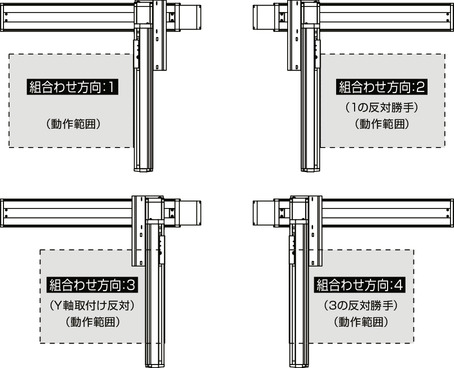
XY combination direction
English version is coming soon!
Model details
| XY combination direction (Note 1) |
Model | ||
|---|---|---|---|
| 1 | ICSB2【ICSPB2】-BQ1M-①-②③-④⑤-T□-⑥-⑦-⑧ | ||
| 2 | ICSB2【ICSPB2】-BQ2M-①-②③-④⑤-T□-⑥-⑦-⑧ | ||
| 3 | ICSB2 [ICSPB2]-BQ3M-①-②③-④⑤-T□-⑥-⑦-⑧ | ||
| 4 | ICSB2 [ICSPB2]-BQ4M-①-②③-④⑤-T□-⑥-⑦-⑧ | ||
(Note 1) For the XY combination direction, see the diagram below. For the contents of ① to ⑧ of the above model numbers, see the table below.
Model code explanation
| number | Contents | Notation |
|---|---|---|
| ① | Encoder Type | WA: Battery-less absolute |
| ② | X-axis stroke | 90: 900mm ~ 300: 3000mm |
| ③ | X-Axis Options |
See option table |
| ④ | Y-axis stroke | 10: 100mm ~ 70: 700mm |
| ⑤ | Y-Axis Options |
See option table |
| ⑥ | Cable length | 3L: 3m 5L: 5m □L: □m |
| ⑦ | Y-axis cable routing | CT: Cable bear |
| ⑧ | Z-axis cable wiring (optional) (Note 2) |
CT: Cable bear |
(Note 2) Please fill in the Z-axis cable wiring column of the model item only if necessary. For external dimensions, refer to
Configuration axis
| Axis Name | Model | Reference page |
|---|---|---|
| X-Axis | ISB [ISPB]-WXMX-①-750-25-②-T□-⑨-③ | |
| Y-Axis | ISB [ISPB]-LXM-①-400-20-④-T□-⑨-⑤ |
(Note) For the above model numbers ① to ⑤, please refer to the symbols in the model numbers in the table above. Note that the stroke is expressed in mm (millimeters).
(Note) The ⑨ in the above model numbers indicates the cable exit direction. For the cable exit direction, refer to page