EC-SRG9


*Note: Some pictures on this page are still Japanese version and the English version pictures are coming soon.
Main Specifications
| item | Contents | ||||
|---|---|---|---|---|---|
| Lead | Ball screw lead (mm) | 6 | 4 | 2 | |
| Horizontal | Payload capacity | Maximum payload (kg) (power saving enabled) | 9 | 15 | 20 |
| Speed/Acceleration | Maximum speed (mm/s) | 360 | 250 | 125 | |
| Minimum speed (mm/s) | 8 | 5 | 3 | ||
| Rated acceleration/deceleration (G) | 0.3 | 0.3 | 0.3 | ||
| Maximum acceleration/deceleration (G) | 0.5 | 0.3 | 0.3 | ||
| vertical | Payload capacity | Maximum payload (kg) (power saving enabled) | 1.5 | 3 | 3 |
| Speed/Acceleration | Maximum speed (mm/s) | 360 | 250 | 125 | |
| Minimum speed (mm/s) | 8 | 5 | 3 | ||
| Rated acceleration/deceleration (G) | 0.3 | 0.3 | 0.3 | ||
| Maximum acceleration/deceleration (G) | 0.3 | 0.3 | 0.3 | ||
| Pressing | Maximum thrust when pressing (N) | 50 | 75 | 150 | |
| Maximum pressing speed (mm/s) | 20 | 20 | 20 | ||
| brake | Brake specifications | Non-excitation electromagnetic brake | |||
| Brake holding force (kgf) | 1.5 | 3 | 3 | ||
| stroke | Minimum stroke (mm) | 50 | 50 | 50 | |
| Maximum stroke (mm) | 200 | 200 | 200 | ||
| Stroke pitch (mm) | 50 | 50 | 50 | ||
| item | Contents |
|---|---|
| Drive system | Ball screw φ6mm rolled C10 |
| Repeated positioning accuracy | ±0.02mm |
| Lost Motion | - (Cannot be indicated due to two-point positioning function.) |
| rod | φ20mm Material: Aluminum, hard anodized |
| Guide shaft | SUJ2 |
| Front bracket | Material: Aluminum, white anodized |
| Rod non-rotation accuracy | ±0.01 degrees |
| Ambient temperature and humidity | 0 to 40°C, 85% RH or less (no condensation) |
| Protection rating | IP20 |
| Vibration and shock resistance | 4.9m/ s2 |
| Overseas compatible standards | CE mark, RoHS directive |
| Motor Type | Pulse motor (□28) (power capacity: max. 2A) |
| Encoder Type | Incremental/Battery-less Absolute |
| Encoder Pulse Number | 800 pulses/rev |
| deadline | Listed on the website [Delivery Date Inquiry] |
Payload table by speed/acceleration
The payload is in kg.
| posture | Horizontal | vertical | |
|---|---|---|---|
| Speed
(mm/s) |
Acceleration (G) | ||
| 0.3 | 0.5 | 0.3 | |
| 0 | 9 | 7 | 1.5 |
| 120 | 9 | 7 | 1.5 |
| 210 | 9 | 6 | 1.5 |
| 255 | 8 | 5 | 1.5 |
| 315 | 7 | 3 | 1 |
| 360 | 6 | 2 | 1 |
| posture | Horizontal | vertical |
|---|---|---|
| Speed
(mm/s) |
Acceleration (G) | |
| 0.3 | 0.3 | |
| 0 | 15 | 3 |
| 80 | 15 | 3 |
| 140 | 15 | 3 |
| 170 | 15 | 3 |
| 210 | 15 | 2 |
| 240 | 8 | 1 |
| 250 | 5 | 1 |
| posture | Horizontal | vertical |
|---|---|---|
| Speed
(mm/s) |
Acceleration (G) | |
| 0.3 | 0.3 | |
| 0 | 20 | 3 |
| 40 | 20 | 3 |
| 85 | 20 | 3 |
| 105 | 18 | 3 |
| 125 | 18 | 3 |
Stroke and maximum speed
(Unit: mm/s)
| Lead (mm) |
50 to 150 (in 50mm increments) |
200 (mm) |
|---|---|---|
| 6 | 360 | 310 |
| 4 | 250 | 200 |
| 2 | 125 | 100 |
Correlation diagram between pressing force and current limit value
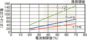
Precautions when performing pressing operation
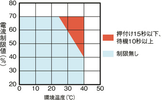
During pressing operations in high temperature environments,
Please use within the limits shown in the graph.
Adaptive Controller
(Note) The EC series has a built-in controller. For details on the built-in controller, see page
International Standards


Selection considerations
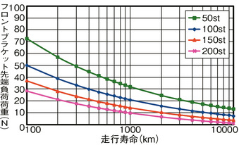
| (1) As the stroke becomes longer, the maximum speed decreases due to the critical rotation speed of the ball screw. Check the maximum speed for the desired stroke in "Stroke and Maximum Speed". (2) The maximum load capacity in "Main Specifications" is shown. (3) The horizontal load capacity is the value when a guide is used to prevent radial and moment loads from being applied to the rod. If no guide is installed, refer to "Front bracket tip load and running life". (4) When performing pressing operation, refer to "Correlation diagram between pressing force and current limit value". The pressing force is a guideline value. Please refer to page for precautions . (5) Cannot be used as a stopper. Please consider using a stopper cylinder (EC-ST9). |
Dimensions
ST: Stroke
ME: Mechanical end
SE: Stroke end
(Note) When performing a return to origin, the rod moves to the ME, so be careful not to let it interfere with surrounding objects.
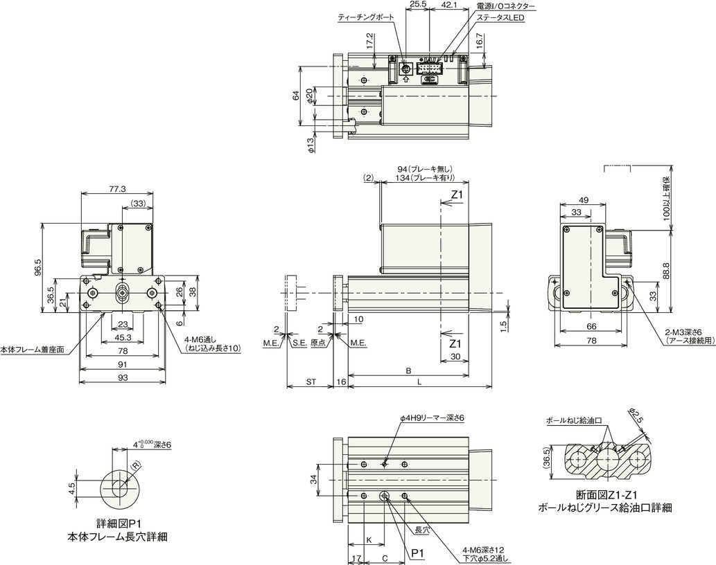
Stroke dimensions
| stroke | 50 | 100 | 150 | 200 |
|---|---|---|---|---|
| L | 155 | 205 | 255 | 305 |
| B | 130 | 180 | 230 | 280 |
| C | 44 | 44 | 120 | 120 |
| K | 39 | 39 | 77 | 77 |
Mass by stroke
| stroke | 50 | 100 | 150 | 200 | |
|---|---|---|---|---|---|
| Mass (kg) |
No brakes | 2.0 | 2.4 | 2.9 | 3.3 |
| With brake | 2.2 | 2.6 | 3.1 | 3.5 | |
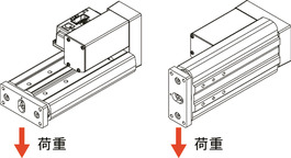
Front bracket tip deflection
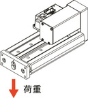
Guide Horizontal

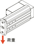
Guide portrait orientation
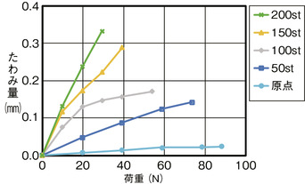
(Note) The amount of deflection at the tip of the front bracket is a guideline.
Front bracket allowable rotation torque
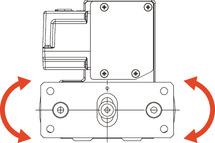
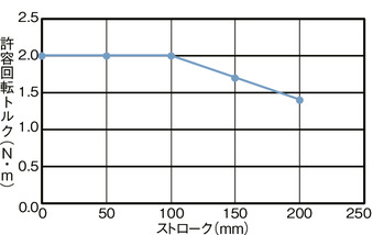
(Note) Use the rotational torque within the allowable range shown in the graph.
Front bracket tip load and running life