EC-S8□AHR


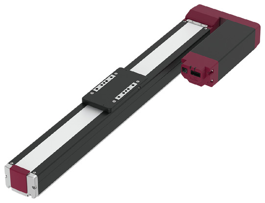
(Note) The photo above shows the motor left-folded specification (ML).
*Note: Some pictures on this page are still Japanese version and the English version pictures are coming soon.
Main Specifications
| item | Contents | |||||
|---|---|---|---|---|---|---|
| Lead | Ball screw lead (mm) | 30 | 20 | 10 | 5 | |
| Horizontal | Payload capacity | Maximum payload (kg) | 20 | 40 | 70 | 110 |
| Speed/Acceleration | Maximum speed (mm/s) | 1200 | 975 | 450 | 225 | |
| Minimum speed (mm/s) | 38 | 25 | 13 | 7 | ||
| Rated acceleration/deceleration (G) | 0.3 | 0.3 | 0.3 | 0.3 | ||
| Maximum acceleration/deceleration (G) | 1 | 1 | 0.5 | 0.3 | ||
| vertical | Payload capacity | Maximum payload (kg) | 2 | 4 | 25 | 55 |
| Speed/Acceleration | Maximum speed (mm/s) | 850 | 650 | 400 | 200 | |
| Minimum speed (mm/s) | 38 | 25 | 13 | 7 | ||
| Rated acceleration/deceleration (G) | 0.3 | 0.3 | 0.3 | 0.3 | ||
| Maximum acceleration/deceleration (G) | 0.5 | 0.5 | 0.5 | 0.3 | ||
| Pressing | Maximum thrust when pressing (N) | 98 | 147 | 294 | 588 | |
| Maximum pressing speed (mm/s) | 20 | 20 | 20 | 20 | ||
| brake | Brake specifications | Non-excitation electromagnetic brake | ||||
| Brake holding force (kgf) | 2 | 4 | 25 | 55 | ||
| stroke | Minimum stroke (mm) | 50 | 50 | 50 | 50 | |
| Maximum stroke (mm) | 1100 | 1100 | 1100 | 1100 | ||
| Stroke pitch (mm) | 50 | 50 | 50 | 50 | ||
| item | Contents |
|---|---|
| Drive system | Ball screw φ16mm rolled C10 |
| Repeated positioning accuracy | Lead 5/10: ±0.02mm, Lead 20: ±0.03mm, Lead 30: ±0.04mm |
| Lost Motion | - (Cannot be indicated due to two-point positioning function.) |
| base | Dedicated aluminum extrusion (equivalent to A6063SS-T6) Black anodized |
| Linear guide | Direct-acting infinite circulation type |
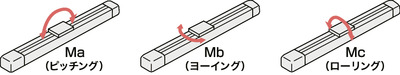
| Static allowable moment | Ma: 327 N・m |
| Mb: 389 N・m | |
| Mc: 629 Nm | |
| Dynamic allowable moment (Note 9) |
Ma: 120 N・m |
| Mb: 143 N・m | |
| Mc: 226 N・m | |
| Ambient temperature and humidity | 0 to 40°C, 85% RH or less (no condensation) |
| Protection rating | IP20 |
| Vibration and shock resistance | 4.9m/ s2 |
| Overseas compatible standards | CE mark, RoHS directive |
| Motor Type | Pulse motor (□56SP) (power capacity: max. 6A) |
| Encoder Type | Incremental/Battery-less Absolute |
| Encoder Pulse Number | 800 pulses/rev |
| deadline | Listed on the website [Delivery Date Inquiry] |
(Note 9) Based on a standard rated life of 5,000 km. The running life will vary depending on the operating conditions and installation. Please check the running life on page
Slider type moment direction
Payload table by speed/acceleration
The unit of payload is kg. Blank spaces mean the item cannot be operated.
| posture | Horizontal | vertical | ||||
|---|---|---|---|---|---|---|
| Speed (mm/s) |
Acceleration (G) | |||||
| 0.3 | 0.5 | 0.7 | 1 | 0.3 | 0.5 | |
| 0 | 20 | 16 | 13 | 12 | 2 | 2 |
| 200 | 20 | 16 | 13 | 12 | 2 | 2 |
| 450 | 20 | 13 | 12 | 11 | 1 | 1 |
| 650 | 14 | 10 | 9 | 8 | 1 | 1 |
| 850 | 9 | 6 | 4 | 2 | 1 | 1 |
| 1000 | 5 | 3 | 2 | 1 | ||
| 1200 | 1 | |||||
| posture | Horizontal | vertical | ||||
|---|---|---|---|---|---|---|
| speed | Acceleration (G) | |||||
| (mm/s) | 0.3 | 0.5 | 0.7 | 1 | 0.3 | 0.5 |
| 0 | 40 | 25 | 20 | 20 | 4 | 4 |
| 200 | 40 | 25 | 20 | 20 | 4 | 4 |
| 300 | 40 | 25 | 20 | 16 | 4 | 4 |
| 400 | 35 | 22 | 18 | 12 | 1 | 1 |
| 650 | 18 | 9 | 4 | 3 | 1 | 1 |
| 800 | 7 | 3 | 1 | |||
| 900 | 5 | 1 | ||||
| 975 | 4 | |||||
| posture | Horizontal | vertical | ||
|---|---|---|---|---|
| speed | Acceleration (G) | |||
| (mm/s) | 0.3 | 0.5 | 0.3 | 0.5 |
| 0 | 70 | 70 | 25 | 25 |
| 100 | 70 | 70 | 25 | 25 |
| 200 | 60 | 50 | 14 | 14 |
| 300 | 45 | 30 | 7 | 7 |
| 400 | 15 | 9 | 2 | 1 |
| 450 | 11 | 2 | ||
| posture | Horizontal | vertical |
|---|---|---|
| Speed (mm/s) |
Acceleration (G) | |
| 0.3 | 0.3 | |
| 0 | 110 | 55 |
| 50 | 110 | 55 |
| 75 | 110 | 30 |
| 135 | 110 | 18 |
| 175 | 70 | 11 |
| 200 | 40 | 3 |
| 225 | 10 | |
Stroke and maximum speed
(Unit: mm/s)
| Lead (mm) |
50 to 700 (in 50mm increments) |
750 (mm) |
800 (mm) |
850 (mm) |
900 (mm) |
950 (mm) |
1000 (mm) |
1050 (mm) |
1100 (mm) |
|---|---|---|---|---|---|---|---|---|---|
| 30 | 1200<850> | 1160<850> | 1040<850> | 940<850> | 860<850> | 780 | 720 | 660 | |
| 20 | 975<650> | 880<650> | 780<650> | 700<650> | 640 | 580 | 530 | 480 | 440 |
| 10 | 450<400> | 430<400> | 380 | 340 | 310 | 280 | 260 | 240 | 220 |
| 5 | 225<200> | 215<200> | 190 | 170 | 150 | 140 | 130 | 115 | 110 |
(Note) < > indicates vertical use.
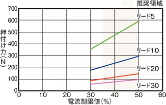
Correlation diagram between pressing force and current limit value
Adaptive Controller
(Note) The EC series has a built-in controller. For details on the built-in controller, see page
International Standards


Selection considerations
| (1) When the stroke is long, the maximum speed decreases due to the critical speed of the ball screw. Check the maximum speed for the desired stroke in "Stroke and maximum speed". (2) The maximum load capacity in "Main specifications" is indicated. For details, refer to "Load capacity by speed and acceleration table". (3) When performing a pressing operation, refer to "Correlation diagram of pressing force and current limit value". The pressing force is a guideline value. For points of caution, refer to page . (4) Duty ratio must be limited depending on the ambient temperature used. For details, refer to page . (5) Caution is required depending on the mounting position. For details, refer to page . (6) The guideline for the overhang load length is 400 mm or less in the Ma, Mb, and Mc directions (800 mm or less for double slider specifications). For the overhang load length, refer to the explanation on page . (7) The center of gravity of the mounting object should be 1/2 or less of the overhang distance. Even if the overhang distance and load moment are within the allowable values, if abnormal vibrations or noise occur during operation, relax the operating conditions. (8) For ordering models and precautions when using double slider specifications, refer to page . (9) When connecting RCON-EC connection specifications (ACR) to an EC connection unit (RCON-EC-4), there is a limit to the number of units that can be connected. For details, refer to page |
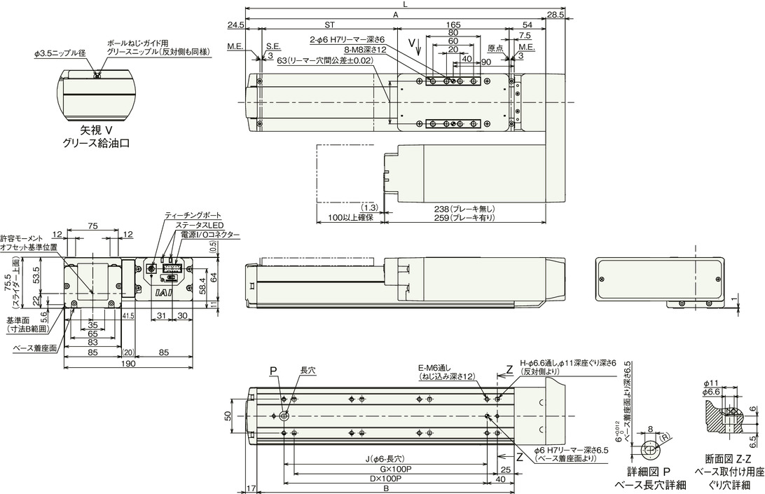
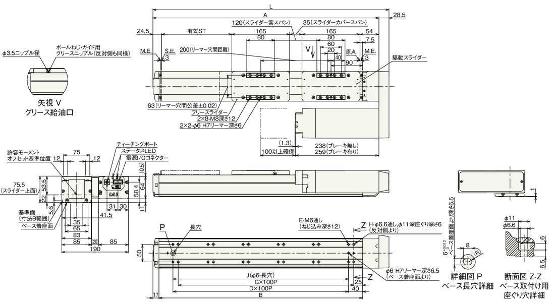
Dimensions
ST: Stroke
ME: Mechanical end
SE: Stroke end
(Note) When performing origin return, the slider will move to the ME, so please be careful not to interfere with the surroundings.
(Note) Pay attention to the length of the mounting bolts. When using mounting screws on the back of the base, if the bolts are long, they may interfere with the internal parts, causing abnormal sliding or damage to the parts.
(Note) If you want to secure the actuator using the through-holes in the base, you will need to remove the side cover and stainless steel sheet.
(Note) For strokes of 50/100, some through-holes cannot be used. Please install the main body using the screw holes on the bottom of the base.
(Note) The diagram below shows the motor left-side reverse specification (ML).
Stroke dimensions
| stroke | 50 | 100 | 150 | 200 | 250 | 300 | 350 | 400 | 450 | 500 | 550 | 600 | 650 | 700 | 750 | 800 | 850 | 900 | 950 | 1000 | 1050 | 1100 |
|---|---|---|---|---|---|---|---|---|---|---|---|---|---|---|---|---|---|---|---|---|---|---|
| L | 322 | 372 | 422 | 472 | 522 | 572 | 622 | 672 | 722 | 772 | 822 | 872 | 922 | 972 | 1022 | 1072 | 1122 | 1172 | 1222 | 1272 | 1322 | 1372 |
| A | 293.5 | 343.5 | 393.5 | 443.5 | 493.5 | 543.5 | 593.5 | 643.5 | 693.5 | 743.5 | 793.5 | 843.5 | 893.5 | 943.5 | 993.5 | 1043.5 | 1093.5 | 1143.5 | 1193.5 | 1243.5 | 1293.5 | 1343.5 |
| B | 230 | 280 | 330 | 380 | 430 | 480 | 530 | 580 | 630 | 680 | 730 | 780 | 830 | 880 | 930 | 980 | 1030 | 1080 | 1130 | 1180 | 1230 | 1280 |
| D | 1 | 2 | 2 | 3 | 3 | 4 | 4 | 5 | 5 | 6 | 6 | 7 | 7 | 8 | 8 | 9 | 9 | 10 | 10 | 11 | 11 | 12 |
| E | 4 | 6 | 6 | 8 | 8 | 10 | 10 | 12 | 12 | 14 | 14 | 16 | 16 | 18 | 18 | 20 | 20 | 22 | 22 | 24 | 24 | 26 |
| G | 1 | 2 | 2 | 3 | 3 | 4 | 4 | 5 | 5 | 6 | 6 | 7 | 7 | 8 | 8 | 9 | 9 | 10 | 10 | 11 | 11 | 12 |
| H | 4 | 6 | 6 | 8 | 8 | 10 | 10 | 12 | 12 | 14 | 14 | 16 | 16 | 18 | 18 | 20 | 20 | 22 | 22 | 24 | 24 | 26 |
| J | 100 | 200 | 200 | 300 | 300 | 400 | 400 | 500 | 500 | 600 | 600 | 700 | 700 | 800 | 800 | 900 | 900 | 1000 | 1000 | 1100 | 1100 | 1200 |
Mass by stroke
| stroke | 50 | 100 | 150 | 200 | 250 | 300 | 350 | 400 | 450 | 500 | 550 | 600 | 650 | 700 | 750 | 800 | 850 | 900 | 950 | 1000 | 1050 | 1100 | |
|---|---|---|---|---|---|---|---|---|---|---|---|---|---|---|---|---|---|---|---|---|---|---|---|
| Mass (kg) |
No brakes | 5.8 | 6.1 | 6.4 | 6.7 | 7.0 | 7.3 | 7.6 | 7.9 | 8.2 | 8.5 | 8.8 | 9.1 | 9.4 | 9.7 | 10.0 | 10.3 | 10.6 | 10.9 | 11.2 | 11.5 | 11.8 | 12.1 |
| With brake | 6.6 | 6.9 | 7.2 | 7.5 | 7.8 | 8.1 | 8.4 | 8.7 | 9.0 | 9.3 | 9.6 | 9.9 | 10.2 | 10.5 | 10.8 | 11.1 | 11.4 | 11.7 | 12.0 | 12.3 | 12.6 | 12.9 | |
Main specifications (double slider specifications)
| item | Contents | ||||
|---|---|---|---|---|---|
| Lead | Ball screw lead (mm) | 20 | 10 | 5 | |
| Horizontal | Payload capacity | Maximum payload (kg) | 40 | 63 | 103 |
| Speed/Acceleration | Maximum speed (mm/s) | 650 | 450 | 200 | |
| Minimum speed (mm/s) | 25 | 13 | 7 | ||
| Rated acceleration/deceleration (G) | 0.3 | 0.3 | 0.3 | ||
| Maximum acceleration/deceleration (G) | 0.5 | 0.5 | 0.3 | ||
| vertical | Payload capacity | Maximum payload (kg) | - | 18 | 48 |
| Speed/Acceleration | Maximum speed (mm/s) | - | 200 | 175 | |
| Minimum speed (mm/s) | - | 13 | 7 | ||
| Rated acceleration/deceleration (G) | - | 0.3 | 0.3 | ||
| Maximum acceleration/deceleration (G) | - | 0.5 | 0.3 | ||
| Pressing | Maximum thrust when pressing (N) | 147 | 294 | 588 | |
| Maximum pressing speed (mm/s) | 20 | 20 | 20 | ||
| brake | Brake specifications | Non-excitation electromagnetic brake | |||
| Brake holding force (kgf) | 4 | 25 | 55 | ||
| stroke | Minimum nominal stroke (mm) | 250 | 250 | 250 | |
| Minimum effective stroke (mm) | 50 | 50 | 50 | ||
| Maximum nominal stroke (mm) | 1100 | 1100 | 1100 | ||
| Maximum effective stroke (mm) | 900 | 900 | 900 | ||
| Stroke pitch (mm) | 50 | 50 | 50 | ||
(Note) Nominal stroke: Model stroke
Effective stroke: The stroke that can actually be operated
(Note) Lead 20 cannot be installed vertically.
| item | Contents |
|---|---|
| Drive system | Ball screw φ16mm rolled C10 |
| Repeated positioning accuracy | Lead 5/10: ±0.02mm, Lead 20: ±0.03mm |
| Lost Motion | - (Cannot be indicated due to two-point positioning function.) |
| base | Dedicated aluminum extrusion (equivalent to A6063SS-T6) Black anodized |
| Linear guide | Direct-acting infinite circulation type |
| Static allowable moment | Ma: 2980 N・m |
| Mb: 3560 N・m | |
| Mc: 1260 N・m | |
| Dynamic allowable moment (Note 10) |
Ma: 894 N・m |
| Mb: 1070 N・m | |
| Mc: 368 N・m | |
| Ambient temperature and humidity | 0 to 40°C, 85% RH or less (no condensation) |
| Protection rating | IP20 |
| Vibration and shock resistance | 4.9m/ s2 |
| Overseas compatible standards | CE mark, RoHS directive |
| Motor Type | Pulse motor (□56SP) (power capacity: max. 6A) |
| Encoder Type | Incremental/Battery-less Absolute |
| Encoder Pulse Number | 800 pulses/rev |
| deadline | Listed on the website [Delivery Date Inquiry] |
(Note 10) This applies to a standard rated lifespan of 5,000 km. Actual operating lifespan may vary depending on driving conditions and installation status.
Slider type moment direction

Load capacity by speed and acceleration (double slider type)
The unit of payload is kg. Blank spaces mean the item cannot be operated.
| posture | Horizontal | |
|---|---|---|
| Speed (mm/s) |
Acceleration (G) | |
| 0.3 | 0.5 | |
| 0 | 40 | 25 |
| 200 | 40 | 25 |
| 300 | 40 | 25 |
| 400 | 28 | 15 |
| 650 | 13 | 2 |
| posture | Horizontal | vertica | ||
|---|---|---|---|---|
| Speed (mm/s) |
Acceleration (G) | |||
| 0.3 | 0.5 | 0.3 | 0.5 | |
| 0 | 63 | 63 | 18 | 18 |
| 100 | 63 | 63 | 18 | 18 |
| 200 | 53 | 42 | 7 | 7 |
| 300 | 38 | 23 | ||
| 400 | 8 | 2 | ||
| 450 | 4 | |||
| posture | Horizontal | vertica |
|---|---|---|
| Speed (mm/s) |
Acceleration (G) | |
| 0.3 | 0.3 | |
| 0 | 103 | 48 |
| 50 | 103 | 48 |
| 75 | 103 | 23 |
| 135 | 103 | 11 |
| 175 | 50 | 4 |
| 200 | 20 | |
Stroke and maximum speed (double slider specification)
(Unit: mm/s)
| Lead (mm) |
Nominal stroke | 250-700 | 750 | 800 | 850 | 900 | 950 | 1000 | 1050 | 1100 |
|---|---|---|---|---|---|---|---|---|---|---|
| Effective Stroke | 50–500 | 550 | 600 | 650 | 700 | 750 | 800 | 850 | 900 | |
| (every 50mm) | (mm) | (mm) | (mm) | (mm) | (mm) | (mm) | (mm) | (mm) | ||
| 20 | 650 | 640 | 580 | 530 | 480 | 440 | ||||
| 10 | 450<200> | 430<200> | 380<200> | 340<200> | 310<200> | 280<200> | 260<200> | 240<200> | 220<200> | |
| 5 | 200<175> | 200<175> | 190<175> | 170 | 150 | 140 | 130 | 115 | 110 | |
(Note) < > indicates vertical use.
(Note) Nominal stroke: Model stroke
Effective stroke: The stroke that can actually be operated
Dimensions (double slider type)
ST: Stroke
ME: Mechanical end
SE: Stroke end
Drawing (double slider specification)
(Note) When performing origin return, the slider will move to the ME, so please be careful not to interfere with the surroundings.
(Note) Pay attention to the length of the mounting bolts. When using mounting screws on the back of the base, if the bolts are long, they may interfere with the internal parts, causing abnormal sliding or damage to the parts.
(Note) Connect the sliders using the slider cover span or reamed hole distance dimensions shown in the dimension drawing.
(Note) If you want to secure the actuator using the through-holes in the base, you will need to remove the side cover and stainless steel sheet.
Stroke dimensions
| Nominal stroke | 250 | 300 | 350 | 400 | 450 | 500 | 550 | 600 | 650 | 700 | 750 | 800 | 850 | 900 | 950 | 1000 | 1050 | 1100 |
|---|---|---|---|---|---|---|---|---|---|---|---|---|---|---|---|---|---|---|
| Effective Stroke | 50 | 100 | 150 | 200 | 250 | 300 | 350 | 400 | 450 | 500 | 550 | 600 | 650 | 700 | 750 | 800 | 850 | 900 |
| L | 522 | 572 | 622 | 672 | 722 | 772 | 822 | 872 | 922 | 972 | 1022 | 1072 | 1122 | 1172 | 1222 | 1272 | 1322 | 1372 |
| A | 493.5 | 543.5 | 593.5 | 643.5 | 693.5 | 743.5 | 793.5 | 843.5 | 893.5 | 943.5 | 993.5 | 1043.5 | 1093.5 | 1143.5 | 1193.5 | 1243.5 | 1293.5 | 1343.5 |
| B | 430 | 480 | 530 | 580 | 630 | 680 | 730 | 780 | 830 | 880 | 930 | 980 | 1030 | 1080 | 1130 | 1180 | 1230 | 1280 |
| D | 3 | 4 | 4 | 5 | 5 | 6 | 6 | 7 | 7 | 8 | 8 | 9 | 9 | 10 | 10 | 11 | 11 | 12 |
| E | 8 | 10 | 10 | 12 | 12 | 14 | 14 | 16 | 16 | 18 | 18 | 20 | 20 | 22 | 22 | 24 | 24 | 26 |
| G | 3 | 4 | 4 | 5 | 5 | 6 | 6 | 7 | 7 | 8 | 8 | 9 | 9 | 10 | 10 | 11 | 11 | 12 |
| H | 8 | 10 | 10 | 12 | 12 | 14 | 14 | 16 | 16 | 18 | 18 | 20 | 20 | 22 | 22 | 24 | 24 | 26 |
| J | 300 | 400 | 400 | 500 | 500 | 600 | 600 | 700 | 700 | 800 | 800 | 900 | 900 | 1000 | 1000 | 1100 | 1100 | 1200 |
(Note) Nominal stroke: The stroke listed in the model number.
Effective stroke: The stroke that can actually be operated
Mass by stroke
| Nominal stroke | 250 | 300 | 350 | 400 | 450 | 500 | 550 | 600 | 650 | 700 | 750 | 800 | 850 | 900 | 950 | 1000 | 1050 | 1100 | |
|---|---|---|---|---|---|---|---|---|---|---|---|---|---|---|---|---|---|---|---|
| Effective Stroke | 50 | 100 | 150 | 200 | 250 | 300 | 350 | 400 | 450 | 500 | 550 | 600 | 650 | 700 | 750 | 800 | 850 | 900 | |
| Mass (kg) |
No brakes | 7.7 | 8.0 | 8.3 | 8.6 | 8.9 | 9.2 | 9.5 | 9.8 | 10.1 | 10.4 | 10.7 | 11.0 | 11.3 | 11.6 | 11.9 | 12.2 | 12.5 | 12.8 |
| With brake | 8.5 | 8.8 | 9.1 | 9.4 | 9.7 | 10.0 | 10.3 | 10.6 | 10.9 | 11.2 | 11.5 | 11.8 | 12.1 | 12.4 | 12.7 | 13.0 | 13.3 | 13.6 | |
(Note) Mass is the sum of the single slider specification and 0.8 kg of free slider.
Correlation diagram between pressing force and current limit value (double slider specification)
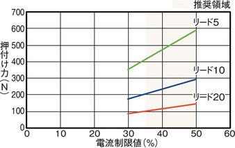
(Note) Same value as the single slider specification.