*Note: Some pictures on this page are still Japanese version and the English version pictures are coming soon.
Main Specifications
| item |
Contents |
| Lead |
Ball screw lead (mm) |
6 |
4 |
2 |
| Horizontal |
Payload capacity |
Maximum payload (kg) |
3.5 |
6 |
9 |
| Speed/Acceleration |
Maximum speed (mm/s) |
420 |
280 |
140 |
| Minimum speed (mm/s) |
8 |
5 |
3 |
| Rated acceleration/deceleration (G) |
0.3 |
0.3 |
0.3 |
| Maximum acceleration/deceleration (G) |
0.5 |
0.3 |
0.3 |
| vertical |
Payload capacity |
Maximum payload (kg) |
1.5 |
2.5 |
3.5 |
| Speed/Acceleration |
Maximum speed (mm/s) |
420 |
280 |
140 |
| Minimum speed (mm/s) |
8 |
5 |
3 |
| Rated acceleration/deceleration (G) |
0.3 |
0.3 |
0.3 |
| Maximum acceleration/deceleration (G) |
0.3 |
0.3 |
0.3 |
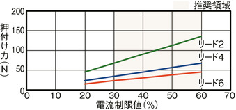
| Pressing |
Maximum thrust when pressing (N) |
45 |
68 |
136 |
| Maximum pressing speed (mm/s) |
20 |
20 |
20 |
| brake |
Brake specifications |
Non-excitation electromagnetic brake |
| Brake holding force (kgf) |
1.5 |
2.5 |
3.5 |
| stroke |
Minimum stroke (mm) |
200 |
200 |
200 |
| Maximum stroke (mm) |
400 |
400 |
400 |
| Stroke pitch (mm) |
50 |
50 |
50 |
| item |
Contents |
| Drive system |
Ball screw φ6mm rolled C10 |
| Repeated positioning accuracy |
±0.02mm |
| Lost Motion |
- (Cannot be indicated due to two-point positioning function.) |
| base |
Dedicated aluminum extrusion (equivalent to A6063SS-T5) Black anodized |
| Linear guide |
Direct-acting infinite circulation type |
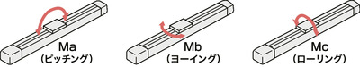
| Static allowable moment |
Ma: 9.5 N・m |
| Mb: 13.5 N・m |
| Mc: 15.1 N・m |
Dynamic allowable moment
(Note 6) |
Ma: 3.8 N・m |
| Mb: 5.4 N・m |
| Mc: 6.1 N・m |
| Ambient temperature and humidity |
0 to 40°C, 85% RH or less (no condensation) |
| Protection rating |
IP20 |
| Vibration and shock resistance |
4.9m/ s2 |
| Overseas compatible standards |
CE mark, RoHS directive |
| Motor Type |
Pulse motor (□28) (power capacity: max. 2.2A) |
| Encoder Type |
Incremental/Battery-less Absolute |
| Encoder Pulse Number |
800 pulses/rev |
| deadline |
Listed on the website [Delivery Date Inquiry] |
(Note 6) Based on a standard rated life of 5,000 km. The running life will vary depending on the operating conditions and installation. Please check the running life on page 1-276 .