EC-RR10


*Note: Some pictures on this page are still Japanese version and the English version pictures are coming soon.
Main Specifications
| item | Contents | |||
|---|---|---|---|---|
| Lead | Ball screw lead (mm) | 5 | 2.5 | |
| Horizontal | Payload capacity | Maximum payload (kg) | 150 | 300 |
| Speed/Acceleration | Maximum speed (mm/s) | 100 | 45 | |
| Minimum speed (mm/s) | 7 | 4 | ||
| Rated acceleration/deceleration (G) | 0.02 | 0.01 | ||
| Maximum acceleration/deceleration (G) | 0.02 | 0.01 | ||
| vertical | Payload capacity | Maximum payload (kg) | 100 | 150 |
| Speed/Acceleration | Maximum speed (mm/s) | 100 | 45 | |
| Minimum speed (mm/s) | 7 | 4 | ||
| Rated acceleration/deceleration (G) | 0.02 | 0.01 | ||
| Maximum acceleration/deceleration (G) | 0.02 | 0.01 | ||
| Pressing | Maximum thrust when pressing (N) | 3000 | 6000 | |
| Maximum pressing speed (mm/s) | 10 | 10 | ||
| brake | Brake Specifications | Non-excitation electromagnetic brake | ||
| Brake holding force (kgf) | 100 | 150 | ||
| stroke | Minimum stroke (mm) | 50 | 50 | |
| Maximum stroke (mm) | 800 | 800 | ||
| Stroke pitch (mm) | 50 | 50 | ||
| Item | Content |
|---|---|
| Drive Method | Ball Screw φ20mm (Lead 2.5) Rolled C10 Ball Screw φ16mm (Lead 5) Rolled C10 |
| Repetition Positioning Accuracy | ±0.02mm |
| Lost Motion | - (Cannot be specified due to two-point positioning function.) |
| Linear Guide | Linear Infinite Circulation Type |
| Rod | φ40mm Material: Aluminum, Hard Anodized Finish |
| Rod Non-Rotation Accuracy (Note 6) | 0 Degrees |
| Operating Ambient Temperature and Humidity | 0 to 40°C, 85% RH or less (no condensation) |
| Protection Rating | IP20 |
| Vibration / Shock Resistance | 4.9m/s2 |
| Overseas Compliance Standards | CE Mark / RoHS Directive |
| Motor Type | Pulse Motor (φ86) (Power Capacity: Max 6A) |
| Encoder Type | Incremental / Battery-less Absolute |
| Encoder Pulse Count | 800 pulse/rev |
| Deadline | Listed on the website under [Delivery Inquiry] |
(Note 6) This is the displacement angle of the rod's rotation direction under no load.
Payload table by speed/acceleration
The payload is in kg.
| posture | Horizontal | vertical |
|---|---|---|
| speed | Acceleration (G) | |
| (mm/s) | 0.02 | 0.02 |
| 0 | 150 | 100 |
| 20 | 150 | 100 |
| 25 | 150 | 90 |
| 30 | 150 | 80 |
| 40 | 150 | 62 |
| 45 | 150 | 55 |
| 50 | 150 | 47 |
| 60 | 150 | 35 |
| 70 | 150 | 25 |
| 80 | 150 | 16 |
| 90 | 150 | 10 |
| 100 | 150 | 5 |
| 姿勢 | 水平 | 垂直 |
|---|---|---|
| 速度 | 加速度(G) | |
| (mm/s) | 0.01 | 0.01 |
| 0 | 300 | 150 |
| 20 | 300 | 150 |
| 25 | 300 | 120 |
| 30 | 300 | 95 |
| 37 | 300 | 60 |
| 40 | 300 | 45 |
| 45 | 300 | 20 |
Stroke and maximum speed
(Unit: mm/s)
| Lead (mm) |
50 to 500 (in 50mm increments) |
550 (mm) |
600 (mm) |
650 (mm) |
700 (mm) |
750 (mm) |
800 (mm) |
|---|---|---|---|---|---|---|---|
| 5 | 100 | 90 | 80 | 70 | 60 | 50 | 45 |
| 2.5 | 45 | 40 | 37 | 30 | 25 | ||
Correlation diagram between pressing force and current limit value
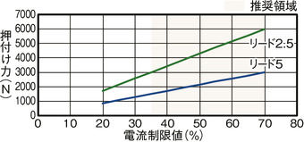
Precautions when performing pressing operation
| Lead | stroke | ||||
|---|---|---|---|---|---|
| Under 600mm | 650mm | 700mm | 750mm | 800mm | |
| Current limit value (%) | |||||
| 5 | 70 | ||||
| 2.5 | 70 | 65 | 60 | 55 | 50 |
Based on the relationship between the buckling load of the ball screw and the deflection of the base,
In the case of a long stroke, the pressing current limit value in the table may be exceeded.
Please try not to do so.
| Current limit value (%) | Number of presses (10,000 times) | |
|---|---|---|
| Lead 5 | Lead 2.5 | |
| 20 | 179280 | 4880 |
| 30 | 53180 | 1440 |
| 40 | 22410 | 610 |
| 50 | 11480 | 310 |
| 60 | 6640 | 180 |
| 70 | 4170 | 110 |
Number of pushes when operated with a push movement of 1 mm
Use the values in the table as a guide for the upper limit.
(Note) Values are based on operating conditions without vibration or shock.
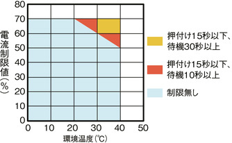
During high thrust pressing operations in high temperature environments,
Please use within the limits shown in the graph.
Adaptive Controller
(Note) The EC series has a built-in controller. For details on the built-in controller, see page
International Standards


Selection considerations
| (1) The maximum speed varies depending on the stroke. Check the maximum speed for the desired stroke in "Stroke and Maximum Speed". (2) The payload in "Main Specifications" is the maximum value. For details, refer to "Payload Table by Speed and Acceleration". (3) The radial cylinder has a built-in guide. For details about the radial load acting on the rod , refer to page . (4) The horizontal payload is when used in conjunction with an external guide. (5) When performing a pressing operation, refer to the "Correlation Diagram of Pressing Force and Current Limit Value". The pressing force is a guideline value. (6) Caution is required depending on the mounting position. For details, refer to page . (7) When connecting the RCON-EC Connection Specification (ACR) to the EC Connection Unit (RCON-EC-4), there is a limit to the number of units that can be connected. For details, refer to page |
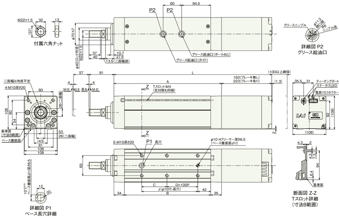
Dimensions
ST: Stroke
ME: Mechanical end
SE: Stroke end
(Note) When performing a return to origin, the rod moves to the ME, so be careful not to let it interfere with the surroundings.
(Note) Pay attention to the length of the mounting bolts. When using mounting screws on the back of the base, if the bolts are long, they may interfere with the internal parts, causing abnormal sliding or damage to the parts.
(Note) The direction of the width across flats cannot be changed.
Stroke dimensions
| stroke | 50 | 100 | 150 | 200 | 250 | 300 | 350 | 400 | 450 | 500 | 550 | 600 | 650 | 700 | 750 | 800 | |
|---|---|---|---|---|---|---|---|---|---|---|---|---|---|---|---|---|---|
| L | No brakes | 462 | 512 | 562 | 612 | 662 | 712 | 762 | 812 | 862 | 912 | 962 | 1012 | 1062 | 1112 | 1162 | 1212 |
| With brake | 522 | 572 | 622 | 672 | 722 | 772 | 822 | 872 | 922 | 972 | 1022 | 1072 | 1122 | 1172 | 1222 | 1272 | |
| A | 299 | 349 | 399 | 449 | 499 | 549 | 599 | 649 | 699 | 749 | 799 | 849 | 899 | 949 | 999 | 1049 | |
| B | 230 | 280 | 330 | 380 | 430 | 480 | 530 | 580 | 630 | 680 | 730 | 780 | 830 | 880 | 930 | 980 | |
| C | 132 | 82 | 132 | 82 | 132 | 82 | 132 | 82 | 132 | 82 | 132 | 82 | 132 | 82 | 132 | 82 | |
| D | 0 | 1 | 1 | 2 | 2 | 3 | 3 | 4 | 4 | 5 | 5 | 6 | 6 | 7 | 7 | 8 | |
| E | 4 | 6 | 6 | 8 | 8 | 10 | 10 | 12 | 12 | 14 | 14 | 16 | 16 | 18 | 18 | 20 | |
| J | 132 | 182 | 232 | 282 | 332 | 382 | 432 | 482 | 532 | 582 | 632 | 682 | 732 | 782 | 832 | 882 | |
Mass by stroke
| stroke | 50 | 100 | 150 | 200 | 250 | 300 | 350 | 400 | 450 | 500 | 550 | 600 | 650 | 700 | 750 | 800 | |
|---|---|---|---|---|---|---|---|---|---|---|---|---|---|---|---|---|---|
| Mass (kg) |
No brakes | 10.5 | 11.2 | 12.0 | 12.8 | 13.6 | 14.4 | 15.2 | 16.0 | 16.8 | 17.6 | 18.4 | 19.1 | 19.9 | 20.7 | 21.5 | 22.3 |
| With brake | 12.0 | 12.8 | 13.6 | 14.4 | 15.2 | 16.0 | 16.7 | 17.5 | 18.3 | 19.1 | 19.9 | 20.7 | 21.5 | 22.3 | 23.1 | 23.9 | |
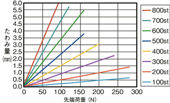
Rod deflection amount (reference value)
Correlation diagram between vertical transport mass and running life
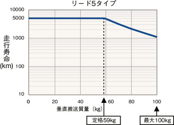
Since the EC-RR10 has a large maximum thrust, when installed vertically,
The life span varies greatly depending on the payload.
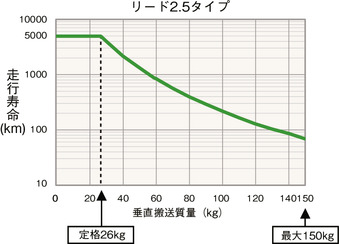
(Note) The rated value is the maximum value for a driving life of 5,000 km.
The maximum number represents the maximum possible operation.
Please note that if the rated values are exceeded, the life span will be reduced as shown in the graph above.
