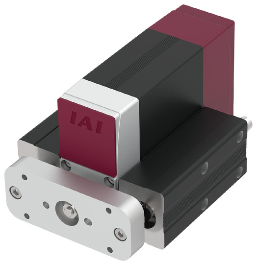
EC-GD5


*Note: Some pictures on this page are still Japanese version and the English version pictures are coming soon.
Main Specifications
| item | Contents | |||||
|---|---|---|---|---|---|---|
| Lead | Ball screw lead (mm) | 16 | 10 | 5 | 2.5 | |
| Horizontal | Payload capacity | Maximum payload (kg) (power saving disabled) | 6.5 | 16 | twenty five | 35 |
| Maximum payload (kg) (power saving enabled) | 6.5 | 15 | twenty five | 35 | ||
| Speed/Acceleration | Maximum speed (mm/s) | 800 | 600 | 300 | 150 | |
| Minimum speed (mm/s) | 40 | 30 | 7 | 4 | ||
| Rated acceleration/deceleration (G) | 0.3 | 0.3 | 0.3 | 0.3 | ||
| Maximum acceleration/deceleration (G) | 1 | 1 | 0.5 | 0.3 | ||
| vertical | Payload capacity | Maximum payload (kg) (power saving disabled) | 1.5 | 2.5 | 6.5 | 6.5 |
| Maximum payload (kg) (power saving enabled) | 1 | 2.5 | 5 | 6.5 | ||
| Speed/Acceleration | Maximum speed (mm/s) | 800 | 600 | 300 | 135 | |
| Minimum speed (mm/s) | 40 | 30 | 7 | 4 | ||
| Rated acceleration/deceleration (G) | 0.3 | 0.3 | 0.3 | 0.3 | ||
| Maximum acceleration/deceleration (G) | 0.5 | 0.5 | 0.5 | 0.3 | ||
| Pressing | Maximum thrust when pressing (N) | 46 | 73 | 150 | 310 | |
| Maximum pressing speed (mm/s) | 40 | 30 | 20 | 20 | ||
| brake | Brake specifications | Non-excitation electromagnetic brake | ||||
| Brake holding force (kgf) | 1.5 | 2.5 | 6.5 | 6.5 | ||
| stroke | Minimum stroke (mm) | 50 | 50 | 50 | 50 | |
| Maximum stroke (mm) | 150 | 150 | 150 | 150 | ||
| Stroke pitch (mm) | 50 | 50 | 50 | 50 | ||
| item | Contents |
|---|---|
| Drive system | Ball screw φ8mm rolled C10 |
| Repeated positioning accuracy | ±0.02mm |
| Lost Motion | - (Cannot be indicated due to two-point positioning function.) |
| Rod non-rotation accuracy | - |
| Running life | 5000km |
| Ambient temperature and humidity | 0 to 40°C, 85% RH or less (no condensation) |
| Protection rating | IP20 |
| Vibration and shock resistance | 4.9m/ s2 |
| Overseas compatible standards | CE mark, RoHS directive |
| Motor Type | Pulse motor (□35) (power capacity: max. 4.2A) |
| Encoder Type | Incremental/Battery-less Absolute |
| Encoder Pulse Number | 800 pulses/rev |
| deadline | Listed on the website [Delivery Date Inquiry] |
Payload capacity by speed and acceleration *Power saving setting is disabled at the time of shipment. For details, see page 1-23 .
Power saving setting disabled (power mode) The unit of payload is kg. Blank spaces mean the operation is disabled.
| posture | Horizontal | vertical | ||||
|---|---|---|---|---|---|---|
| Speed (mm/s) |
Acceleration (G) | |||||
| 0.3 | 0.5 | 0.7 | 1 | 0.3 | 0.5 | |
| 0 | 6.5 | 4 | 3 | 2 | 1.5 | 1.25 |
| 140 | 6.5 | 4 | 3 | 2 | 1.5 | 1.25 |
| 280 | 6.5 | 4 | 3 | 2 | 1.5 | 1.25 |
| 420 | 6.5 | 4 | 2.5 | 1.5 | 1.5 | 1.25 |
| 560 | 5 | 3 | 2 | 1 | 1 | 1 |
| 700 | 3.5 | 1.5 | 1 | 0.5 | 1 | 1 |
| 800 | 1 | 1 | 0.5 | 0.5 | ||
| posture | Horizontal | vertical | ||||
|---|---|---|---|---|---|---|
| Speed (mm/s) |
Acceleration (G) | |||||
| 0.3 | 0.5 | 0.7 | 1 | 0.3 | 0.5 | |
| 0 | 16 | 11 | 7 | 4.5 | 2.5 | 2 |
| 175 | 16 | 11 | 7 | 4.5 | 2.5 | 2 |
| 350 | 12.5 | 7 | 4 | 2.5 | 2.5 | 2 |
| 435 | 9.5 | 5 | 3 | 1.5 | 2 | 2 |
| 525 | 5 | 4 | 2 | 1 | 1.5 | 1 |
| 600 | 4.5 | 2 | 1 | 0.5 | 0.5 | |
| posture | Horizontal | vertical | ||
|---|---|---|---|---|
| Speed (mm/s) |
Acceleration (G) | |||
| 0.3 | 0.5 | 0.3 | 0.5 | |
| 0 | twenty five | twenty two | 6.5 | 4.5 |
| 85 | twenty five | twenty two | 6.5 | 4.5 |
| 130 | twenty five | 20 | 5 | 4.5 |
| 215 | 15 | 15 | 4 | 4 |
| 260 | 10 | 10 | 2 | 2 |
| 300 | 5 | 5 | 1.5 | 1.5 |
| posture | Horizontal | vertical |
|---|---|---|
| Speed (mm/s) |
Acceleration (G) | |
| 0.3 | 0.3 | |
| 0 | 35 | 6.5 |
| 40 | 35 | 6.5 |
| 85 | 35 | 6.5 |
| 105 | 35 | 6.5 |
| 135 | 30 | 2 |
| 150 | 10 | |
Power saving setting enabled (energy saving mode) The unit of payload is kg. Blank spaces mean the operation is disabled.
| posture | Horizontal | vertical | |
|---|---|---|---|
| Speed
(mm/s) |
Acceleration (G) | ||
| 0.3 | 0.7 | 0.3 | |
| 0 | 6.5 | 2.5 | 1 |
| 140 | 6.5 | 2.5 | 1 |
| 280 | 5 | 2 | 1 |
| 420 | 4 | 1 | 0.5 |
| 560 | 2.5 | 0.5 | 0.5 |
| posture | Horizontal | vertical | |
|---|---|---|---|
| Speed
(mm/s) |
Acceleration (G) | ||
| 0.3 | 0.7 | 0.3 | |
| 0 | 15 | 5.5 | 2.5 |
| 175 | 15 | 5.5 | 2.5 |
| 350 | 6 | 2 | 1.5 |
| 435 | 4.5 | 1.5 | 0.5 |
| 525 | 0.5 | ||
| posture | Horizontal | vertical |
|---|---|---|
| Speed
(mm/s) |
Acceleration (G) | |
| 0.3 | 0.3 | |
| 0 | twenty five | 5 |
| 85 | twenty five | 5 |
| 130 | twenty five | 5 |
| 215 | 8 | 2 |
| posture | Horizontal | vertical |
|---|---|---|
| Speed
(mm/s) |
Acceleration (G) | |
| 0.3 | 0.3 | |
| 0 | 35 | 6.5 |
| 40 | 35 | 6.5 |
| 85 | 34 | 6.5 |
| 105 | twenty five | 1 |
Stroke and maximum speed
(Unit: mm/s)
| Lead (mm) |
Power saving settings | 50 to 150 (in 50mm increments) |
|---|---|---|
| 16 | invalid | 800 |
| valid | 560 | |
| 10 | invalid | 600 |
| valid | 525<435> | |
| 5 | invalid | 300 |
| valid | 215 | |
| 2.5 | invalid | 150<135> |
| valid | 105 |
(Note) Values in < > are for vertical use.
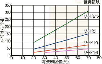
Correlation diagram between pressing force and current limit value
Adaptive Controller
(Note) The EC series has a built-in controller. For details on the built-in controller, see page
International Standards


Selection considerations
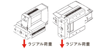
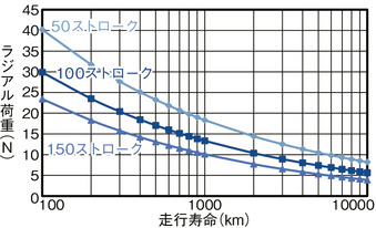
| (1) The payload in the "Main Specifications" is the maximum value. (2) The horizontal payload is the value when a guide is used to prevent radial and moment loads from being applied to the rod. If no guide is installed, refer to "Radial Load and Running Life." (3) If performing a pressing operation, refer to "Correlation Diagram of Pressing Force and Current Limit Value." The pressing force is a guideline value. Please see page for points of caution . |
Dimensions
ST: Stroke
ME: Mechanical end
SE: Stroke end
(Note) When performing a return to origin, the rod moves to the ME, so be careful not to interfere with the surroundings.
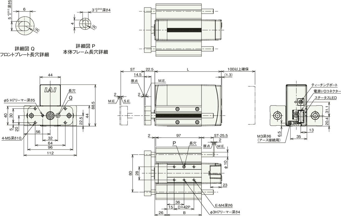
Stroke dimensions
| Encoder Type | incremental | Battery-less absolute | |||||
|---|---|---|---|---|---|---|---|
| stroke | 50 | 100 | 150 | 50 | 100 | 150 | |
| L | No brakes | 141 | 191 | 241 | 166 | 191 | 241 |
| With brake | 191 | 191 | 241 | 204 | 204 | 241 | |
| B | No brakes | 73 | one two three | 173 | 98 | one two three | 173 |
| With brake | one two three | one two three | 173 | 136 | 136 | 173 | |
| D | No brakes | 1 | 2 | 3 | 1 | 2 | 3 |
| With brake | 2 | 2 | 3 | 2 | 2 | 3 | |
| E | No brakes | 4 | 6 | 8 | 4 | 6 | 8 |
| With brake | 6 | 6 | 8 | 6 | 6 | 8 | |
Mass by stroke
| Encoder Type | incremental | Battery-less absolute | |||||
|---|---|---|---|---|---|---|---|
| stroke | 50 | 100 | 150 | 50 | 100 | 150 | |
| Mass (kg) |
No brakes | 2.1 | 2.4 | 2.7 | 2.2 | 2.4 | 2.7 |
| With brake | 2.5 | 2.5 | 2.8 | 2.5 | 2.6 | 2.8 | |
Radial load and running life