EC-GD3


*Note: Some pictures on this page are still Japanese version and the English version pictures are coming soon.
Main Specifications
| item | Contents | ||||
|---|---|---|---|---|---|
| Lead | Ball screw lead (mm) | 6 | 4 | 2 | |
| Horizontal | Payload capacity | Maximum payload (kg) | 1.5 | 3 | 6 |
| Speed/Acceleration | Maximum speed (mm/s) | 300 | 200 | 100 | |
| Minimum speed (mm/s) | 8 | 5 | 3 | ||
| Rated acceleration/deceleration (G) | 0.3 | 0.3 | 0.3 | ||
| Maximum acceleration/deceleration (G) | 0.3 | 0.3 | 0.3 | ||
| vertical | Payload capacity | Maximum payload (kg) | 0.5 | 1 | 2 |
| Speed/Acceleration | Maximum speed (mm/s) | 300 | 200 | 75 | |
| Minimum speed (mm/s) | 8 | 5 | 3 | ||
| Rated acceleration/deceleration (G) | 0.3 | 0.3 | 0.3 | ||
| Maximum acceleration/deceleration (G) | 0.3 | 0.3 | 0.3 | ||
| Pressing | Maximum thrust when pressing (N) | 14 | twenty one | 42 | |
| Maximum pressing speed (mm/s) | 20 | 20 | 5 | ||
| brake | Brake specifications | Non-excitation electromagnetic brake | |||
| Brake holding force (kgf) | 0.5 | 1 | 2 | ||
| stroke | Minimum stroke (mm) | 30 | 30 | 30 | |
| Maximum stroke (mm) | 100 | 100 | 100 | ||
| Stroke pitch (mm) (30 to 50ST) | 20 | 20 | 20 | ||
| Stroke pitch (mm) (50 to 100ST) | twenty five | twenty five | twenty five | ||
| item | Contents |
|---|---|
| Drive system | Ball screw φ6mm rolled C10 |
| Repeated positioning accuracy | ±0.02mm |
| Lost Motion | - (Cannot be indicated due to two-point positioning function.) |
| Rod non-rotation accuracy (Note 8) | - |
| Running life (Note 9) | 5000km |
| Ambient temperature and humidity | 0 to 40°C, 85% RH or less (no condensation) |
| Protection rating | IP20 |
| Vibration and shock resistance | 4.9m/ s2 |
| Overseas compatible standards | CE mark, RoHS directive |
| Motor Type | Pulse motor (□20) (power capacity: maximum 1.25A) |
| Encoder Type | Incremental/Battery-less Absolute |
| Encoder Pulse Number | 16384 pulses/rev |
| deadline | Listed on the website [Delivery Date Inquiry] |
(Note 8) Indicates the rod rotational displacement angle under no load.
(Note 9) The operating life will vary depending on the operating conditions and installation conditions.
Payload table by speed/acceleration
Standard grease specifications. The unit of payload is kg. Blank spaces indicate that the product cannot be operated.
| posture | Horizontal | vertical |
|---|---|---|
| speed | Acceleration (G) | |
| (mm/s) | 0.3 | 0.3 |
| 0 | 1.5 | 0.5 |
| 50 | 1.5 | 0.5 |
| 100 | 1.5 | 0.5 |
| 150 | 1.5 | 0.5 |
| 200 | 1.5 | 0.3 |
| 250 | 1 | 0.3 |
| 300 | 1 | 0.2 |
| posture | Horizontal | vertical |
|---|---|---|
| speed | Acceleration (G) | |
| (mm/s) | 0.3 | 0.3 |
| 0 | 3 | 1 |
| 50 | 3 | 1 |
| 100 | 3 | 1 |
| 150 | 2 | 0.5 |
| 200 | 1 | 0.3 |
| posture | Horizontal | vertical |
|---|---|---|
| speed | Acceleration (G) | |
| (mm/s) | 0.3 | 0.3 |
| 0 | 6 | 2 |
| twenty five | 6 | 2 |
| 50 | 4 | 1.5 |
| 75 | 2 | 0.5 |
| 100 | 0.5 | |
If the ambient temperature is below 5°C, use the product at or below the speeds listed below.
・Lead 6: 200mm/s or less
・Lead 4: 150mm/s or less
・Lead 2: 50mm/s or less
Food grade grease specifications. The unit of payload is kg. Blank spaces indicate that the product cannot be operated.
| posture | Horizontal | vertical |
|---|---|---|
| speed | Acceleration (G) | |
| (mm/s) | 0.3 | 0.3 |
| 0 | 1.5 | 0.5 |
| 50 | 1.5 | 0.5 |
| 100 | 1.5 | 0.5 |
| 150 | 1.5 | 0.5 |
| 200 | 1.5 | 0.3 |
| 250 | 1 | |
| posture | Horizontal | vertical |
|---|---|---|
| speed | Acceleration (G) | |
| (mm/s) | 0.3 | 0.3 |
| 0 | 3 | 1 |
| 50 | 3 | 1 |
| 100 | 3 | 0.5 |
| 150 | 0.5 | 0.3 |
| posture | Horizontal | vertical |
|---|---|---|
| speed | Acceleration (G) | |
| (mm/s) | 0.3 | 0.3 |
| 0 | 6 | 2 |
| twenty five | 6 | 2 |
| 50 | 1.5 | 0.5 |
| 75 | 0.5 | |
Stroke and maximum speed
(Unit: mm/s)
| Lead (mm) |
30 (mm) |
50 (mm) |
75 (mm) |
100 (mm) |
|---|---|---|---|---|
| 6 | 300 | |||
| 4 | 200 | |||
| 2 | 100<75> | |||
(Note) < > indicates vertical use.
Correlation diagram between pressing force and current limit value
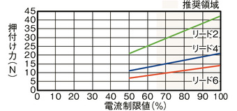
Precautions when performing pressing operation
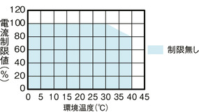
When performing high thrust pressing operations in a high temperature environment, please use within the limit values shown in the graph.
Adaptive Controller
(Note) The EC series has a built-in controller. For details on the built-in controller, see page
International Standards


Selection considerations
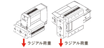
| (1) The "Main Specifications" transport capacity is the maximum value. For details, refer to the "Transport Capacity by Speed and Acceleration Table." (2) The horizontal transport capacity is the value when a guide is used to prevent radial and moment loads from being applied to the rod. If no guide is installed, refer to "Front Bracket Tip Load and Running Life." (3) If performing a pressing operation, refer to the "Correlation Diagram of Pressing Force and Current Limit Value." The pressing force is a guideline value. |
Dimensions
ST: Stroke
ME: Mechanical end
SE: Stroke end
(Note) When performing a return to origin, the rod moves to the ME, so be careful not to let it interfere with surrounding objects.
Note: Make sure to secure the cable so that the base of the cable does not move.
The cable can be separated and replaced (connected via the connector inside the cable box).
The standard direction for the actuator cable to exit is from the rear.
The cable exit direction (optional) can be changed by changing the direction of the cable box.
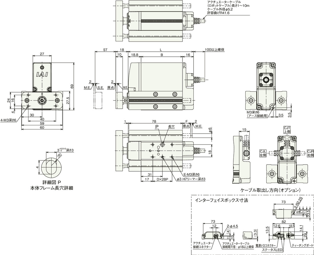
Stroke dimensions
| stroke | 30 | 50 | 75 | 100 | |
|---|---|---|---|---|---|
| L | No brakes | 95 | 115 | 140 | 165 |
| With brake | 140 | 140 | 140 | 165 | |
| B | No brakes | 60.2 | 80.2 | 105.2 | 130.2 |
| With brake | 105.2 | 105.2 | 105.2 | 130.2 | |
| D | No brakes | 1 | 1 | 2 | 3 |
| With brake | 2 | 2 | 2 | 3 | |
| E | No brakes | 4 | 4 | 6 | 8 |
| With brake | 6 | 6 | 6 | 8 | |
| F | 0 | 9.3 | 34.3 | 59.3 | |
Mass by stroke
| stroke | 30 | 50 | 75 | 100 | |
|---|---|---|---|---|---|
| Mass (kg) |
No brakes | 0.61 | 0.66 | 0.73 | 0.80 |
| With brake | 0.78 | 0.79 | 0.81 | 0.88 | |
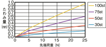
Rod deflection amount (reference value)
Guide Horizontal
Guide portrait orientation

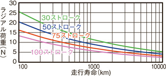
Radial load and running life