The IX SCARA robot implements the X-SEL controller. The X-SEL controller will make additional commands available, that are exclusive only to the IX SCARA. With the expanded command set also comes three additional tools that are described in the following notes. In addition the home procedure has been greatly simplified from the IH model.
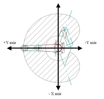
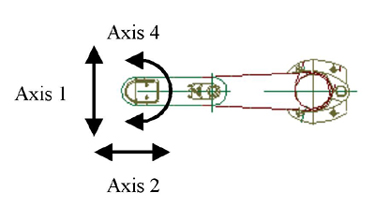
The above picture demonstrates the typical Cartesian coordinate system layout for the SCARA. Based on the position of arm1 and arm2, the SCARA Main CPU converts their radian coordinates to rectangular (shown below) for the above coordinate system.
Work Coordinates
Work coordinates allow the programmer to adjust for any physical shifts of the robot relative to its environment/mounting as shown above. This will make reteaching points unnecessary should the robot shift during operation. There are 31 programmable Work Coordinates which can be enabled or disabled in a program with the new IX Super SEL commands.
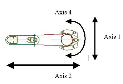
Axes of the Work Coordinate Data
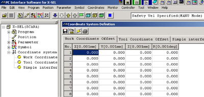
Work Coordinate Table
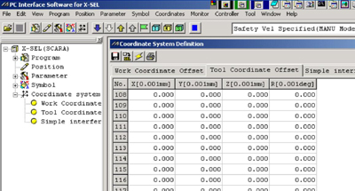
Tool Coordinates
Tool coordinates allow the programmer to adjust for the size and orientation the end effectors mounted on the IX SCARA robot. Activating a Tool coordinate will give the actual coordinates of the tool tip as opposed to the coordinates of the IX mounting tip. The programmer can now use different size toolings on the same set of taught points.(127 points)
Tool Coordinate Axis
Tool Coordinate Axis
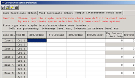
Interference Zones
Interference coordinates allow the programmer set up safety areas that will trigger an output or warnings of varying levels. Two coordinates are used to set up a range for each axis. (10 Zones).
Error Types:
0:No-error
1:Message level error (non-fatal)
2:Operation release level error (fatal)
Interference Coordinate Table
Homing
Homing the IX SCARA robot is simple. The Abs. Encoder Reset menu guides the operator through each step.
Calibration is done through the jogging portion of the procedure and can be fixed into position the home location with a pin. The Homing Kit (pins and theta bracket) should be order at time of purchase or a 4mm reamer/dowel/tapered pin can be used.
The red arrow will point to the button that should be clicked. Press the buttons once in order as prompted by the arrow.
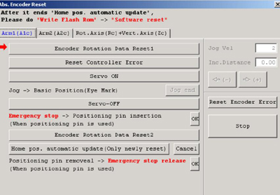
IX Absolute Homing Menu