EC-ST9


*Note: Some pictures on this page are still Japanese version and the English version pictures are coming soon.
Main Specifications
| item | Contents | |||
|---|---|---|---|---|
| Lead | Ball screw lead (mm) | 4 | 2 | |
| vertical | Payload capacity (Note 7) | Payload capacity (kg) (power saving effective) | 1 | 3 |
| Speed/Acceleration | Maximum speed (mm/s) | 250 | 125 | |
| Minimum speed (mm/s) | 5 | 3 | ||
| Rated acceleration/deceleration (G) | 0.3 | 0.3 | ||
| Maximum acceleration/deceleration (G) | 0.3 | 0.3 | ||
| brake | Brake Specifications | Non-excitation electromagnetic brake | ||
| Brake holding force (kgf) | 3 | 3 | ||
| stroke | Minimum stroke (mm) | 30 | 30 | |
| Maximum stroke (mm) | 50 | 50 | ||
| Stroke pitch (mm) | 20 | 20 | ||
(Note 7) When operating at maximum speed and maximum acceleration/deceleration.
| item | Contents |
|---|---|
| Drive system | Ball screw φ6mm rolled C10 |
| Repeated positioning accuracy | ±0.15mm |
| Lost Motion | - (Cannot be indicated due to two-point positioning function.) |
| rod | φ20mm Material: Aluminum, hard anodized |
| Guide shaft | S45C |
| Front bracket | S50C |
| Ambient temperature and humidity | 0 to 40°C, 85% RH or less (no condensation) |
| Protection rating | IP20 |
| Vibration and shock resistance | 4.9m/ s2 |
| Overseas compatible standards | CE mark, RoHS directive |
| Motor Type | Pulse motor (□28) (power capacity: max. 2A) |
| Encoder Type | Incremental/Battery-less Absolute |
| Encoder Pulse Number | 800 pulses/rev |
| deadline | Listed on the website [Delivery Date Inquiry] |
Payload table by speed/acceleration
The payload is in kg.
| posture | vertical |
|---|---|
| speed | Acceleration (G) |
| (mm/s) | 0.3 |
| 0 | 3 |
| 80 | 3 |
| 140 | 2.5 |
| 170 | 2.5 |
| 210 | 2 |
| 240 | 1 |
| 250 | 1 |
| posture | vertical |
|---|---|
| speed | Acceleration (G) |
| (mm/s) | 0.3 |
| 0 | 3 |
| 40 | 3 |
| 85 | 3 |
| 105 | 3 |
| 125 | 3 |
Adaptive Controller
(Note) The EC series has a built-in controller. For details on the built-in controller, see page
International Standards


Selection considerations
| (1) The standard specification home position is set on the opposite side to the motor. Check the home position in the dimension drawing. (2) Do not use the product with a thrust from a conveyor or other device that is greater than the allowable load of 200N. (3) A floating mechanism is provided between the rod end bracket and the front bracket to absorb shock. Therefore, the rod end bracket has play in the axial and rotational directions. This product is designed exclusively for stopper use, so if you are using it for positioning purposes, please consider EC-SRG9. |
Dimensions
ST: Stroke
ME: Mechanical end
SE: Stroke end
(Note) When performing a return to origin, the rod moves to the ME, so be careful not to let it interfere with surrounding objects.
(Note) Please note that if you select the brake option with a stroke of 30 mm, the motor unit will protrude beyond the front bracket.
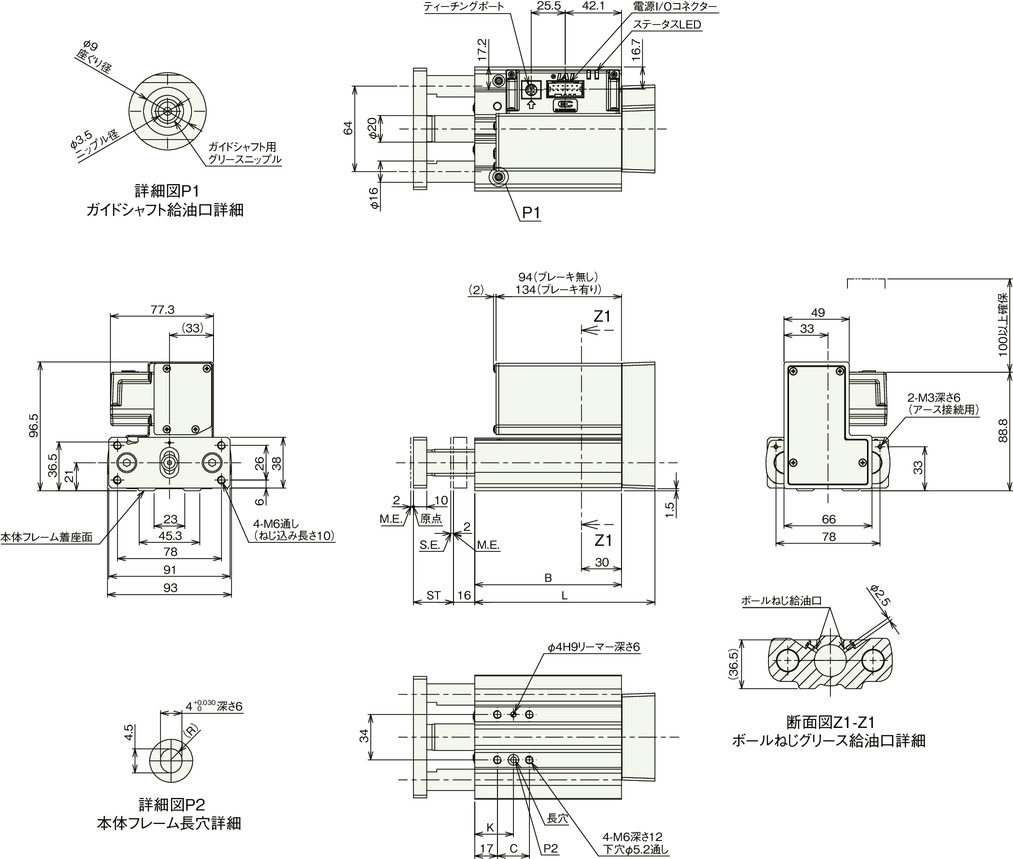
Stroke dimensions
| stroke | 30 | 50 |
|---|---|---|
| L | 135 | 155 |
| B | 110 | 130 |
| C | twenty four | 44 |
| K | 29 | 39 |
Mass by stroke
| stroke | 30 | 50 | |
|---|---|---|---|
| Mass (kg) |
No brakes | 1.8 | 2.0 |
| With brake | 2.1 | 2.3 | |
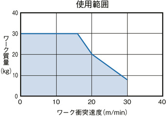
Correlation diagram between workpiece mass and workpiece collision speed
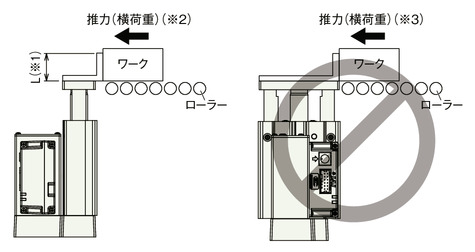
(※1) Please use within L dimension 50mm.
(※2) The thrust from conveyors, etc. should not exceed the allowable load of 200N.
(*3) The actuator cannot withstand loads from the side.