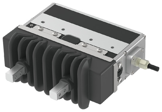
EC-GRBP13□W


*Note: Some pictures on this page are still Japanese version and the English version pictures are coming soon.
Main Specifications
| item | Contents | ||
|---|---|---|---|
| Reduction ratio | M | L | |
| Lead | Trapezoidal thread lead (mm) | 2 | 2 |
| Pulley reduction ratio | 1.36 | 2.14 | |
| Grasping Action | Maximum gripping force (N) (both sides) | 154 | 258 |
| Gripping speed (mm/s) (one side) | 5 | 5 | |
| Approach movement | Maximum speed (mm/s) (one side) | 100 | 63 |
| Minimum speed (mm/s) (one side) | 5 | 5 | |
| Rated acceleration/deceleration (G) (one side) | 0.3 | 0.3 | |
| Maximum acceleration/deceleration (G) (one side) | 0.3 | 0.3 | |
| brake | Brake Specifications | - | - |
| Brake holding force (N) | - | - | |
| stroke | Minimum stroke (mm) (one side) | 20 | 20 |
| Maximum stroke (mm) (one side) | 20 | 20 | |
| item | Contents | |
|---|---|---|
| Drive system | Timing belt + left and right trapezoidal slide screw | |
| Repeated positioning accuracy | ±0.05mm | |
| Lost Motion | - (Cannot be indicated due to two-point positioning function.) | |
| Backlash (one side) | 0.15mm or less | |
| Linear guide | Finite Guide | |
| Static allowable moment | Ma: 7.50 N・m | |
| Mb: 7.50 N・m | ||
| Mc: 15.3 N・m | ||
| Main parts material (Note 10) |
Frame | Aluminum, black anodized |
| Finger Attachment | Stainless steel (SCS13) solution heat treatment | |
| Actuator Cable | Polyvinyl chloride (PVC) | |
| Vertical allowable load (Note 11) | 898N | |
| Ambient temperature and humidity | 0 to 40°C, 85% RH or less (no condensation) | |
| Protection rating | IP54 equivalent | |
| Vibration and shock resistance | 4.9m/ s2 | |
| Overseas compatible standards | CE mark, RoHS directive | |
| Motor Type | Pulse motor (□28) (power capacity: max. 2A) | |
| Encoder Type | Incremental/Battery-less Absolute | |
| Encoder Pulse Number | 16384 pulses/rev | |
| deadline | Listed on the website [Delivery Date Inquiry] | |
(Note 10) For details, please refer to page
(Note 11) If the product is used under a load exceeding the above values, it may shorten its lifespan or cause damage.
Adaptive Controller
(Note) The EC series has a built-in controller. For details on the built-in controller, see page
International Standards


Selection considerations
| (1) The maximum opening and closing speed of the "main specifications" indicates the operating speed of one side. The relative operating speed is twice the value. (2) The maximum gripping force of the "main specifications" is the total value of the gripping force of both fingers when the gripping point distance is 40 and the overhang distance is 40. For the actual workpiece mass that can be transported, please refer to "Confirming the gripping point distance". (3) When gripping a workpiece , be sure to use the pressing operation. (4) The self-locking mechanism maintains the gripping force even when the power is turned off. (However, it does not guarantee that the workpiece will not fall.) When removing a workpiece being gripped when the power is turned off, turn the opening and closing screw on the side or remove the finger attachment to remove the workpiece. (5) The duty ratio must be limited depending on the ambient temperature. For details, refer to page . (6) If the waterproof joint cable specification (option model: JYW) is selected, the attached actuator cable will be a waterproof joint cable specification. |
Dimensions
SE: Stroke end
*1 It is plugged with a set screw to prevent foreign matter from getting in. Please remove it when installing the intake and exhaust joint (normally not used).
*2 If the connector connection is subject to vibration or other unstable position, secure the cable with a cable tie or similar to prevent the connector connection from moving.
Make sure to align the arrow printed on the connector and then insert it all the way in.
(Note) The standard setting is that the open side is the home position. If you wish to set the home position to the closed side, please specify the option (model: NM).
(Note) The actuator cable exit direction is standard at the rear, but can be changed to one of four directions as an option.
(Note) The interface box is not dust-proof or water-proof. Install it in a place where it will not get wet.

Mass by stroke
| item | Contents |
|---|---|
| mass | 1.03kg |
Check gripping distance
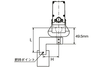
Please use the product so that the distance (L, H) from the finger (claw) mounting surface to the gripping point is within the range shown in the graph.
(Note) If the limit range is exceeded, excessive moment will be applied to the finger sliding part and internal mechanism, which may adversely affect the service life.
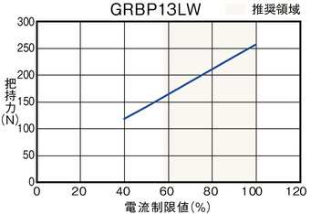
Grip Force
■Correlation diagram between gripping force and current limit value
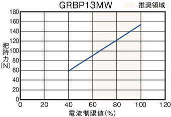
(Note) This is the total value for both fingers when the gripping point distance (L, H) is 40.
(Note) These are approximate values. There is a variation of about 0 to 60%. The possibility of variation is particularly high when the current limit value is set outside the recommended range (the colored range of the graph).
(Note) When gripping (pushing), the speed is fixed at 5 mm/s.
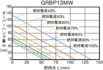
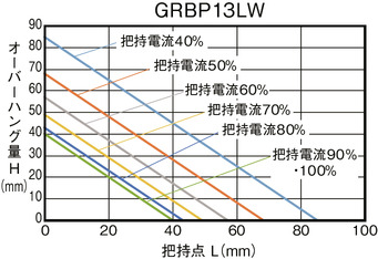
■ Guideline for gripping point distance and gripping force
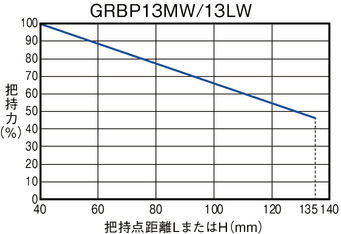
(Note) The gripping force at the extension position is shown when the maximum gripping force is 100%. The results may vary depending on the rigidity of the finger attachment used.