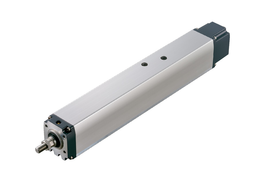
RCP5W-RA7C


Actuator Specification
| Model | Lead (mm) |
Connection Controller |
Maximum payload capacity | Maximum pressing force (N) |
Stroke (mm) |
||
|---|---|---|---|---|---|---|---|
| Level (kg) | Vertical (kg) | ||||||
| Standard Specifications |
RCP5W-RA7C-WA-56P-16-①-②-③-④ | 16 | High output enabled | 40 | 7 | 219 | 50 to 500 (every 50 mm) |
| High output disabled | 5 | ||||||
| RCP5W-RA7C-WA-56P-8-①-②-③-④ | 8 | High output enabled | 50 | 15 | 437 | ||
| High output disabled | |||||||
| RCP5W-RA7C-WA-56P-4-①-②-③-④ | 4 | High output enabled | 70 | twenty five | 875 | ||
| High output disabled | |||||||
| High thrust specifications |
RCP5W-RA7C-WA-56SP-4-①-P4-③-④ | 4 | High output enabled | - | 45 | 1030 | |
| High output disabled | |||||||
Symbol explanation ① Stroke ② Applicable controller ③ Cable length ④ Option
| Lead (mm) |
Connection Controller |
50 (mm) |
100 to 500 (every 50 mm) |
|---|---|---|---|
| 16 | High output enabled | 500【450<300>】 | 560<400>【450<300>】 |
| High output disabled | 420<350> | ||
| 8 | High output enabled | 340<280>【300<250>】 | |
| High output disabled | 210<210> | ||
| 4 | High output enabled | 170<140>【150<125>】 | |
| High output disabled | 140<110> | ||
| 4 (high thrust) |
High output enabled | <80>【<80>】 | |
| High output disabled | - | ||
(Unit: mm/s)
(Note) < > indicates vertical use.
(Note) The values in brackets [ ] apply when used at an ambient temperature of 5°C or less.
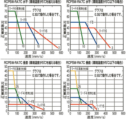
Correlation diagram between speed and payload
If the environmental temperature is below 5°C, the speed will be slower than when it is above 5°C.
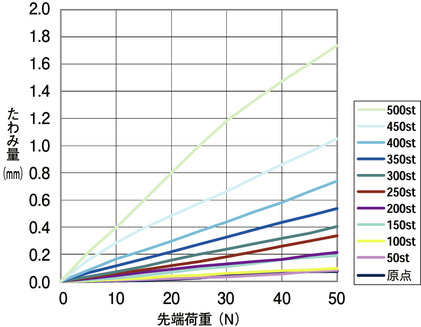
RCP5W-RA7C Rod deflection amount
The table below shows the amount of rod deflection measured when the rod is placed vertically and a load is applied to the tip of the rod.
Actuator Specifications
| item | Contents |
|---|---|
| Drive system | Ball screw φ12mm rolled C10 |
| Repeated positioning accuracy | ±0.02mm |
| Lost Motion | Less than 0.1 mm |
| rod | φ25mm Stainless steel pipe |
| Rod non-rotation accuracy (Note 2) | 0 degrees |
| Rod end allowable load/allowable torque | Please refer to the stroke-specific dimension table and page |
| Rod tip overhang distance | Under 100mm |
| Protective structure | IP67 |
| Ambient temperature and humidity | 0 to 40°C, 85% RH or less (no condensation) |
(Note 2) Indicates the angle of displacement in the rod rotation direction under no load.
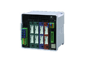
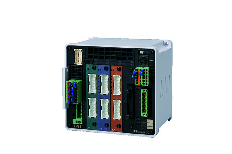
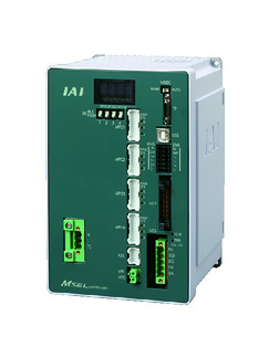
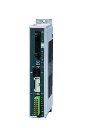
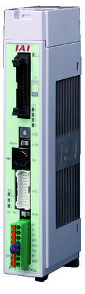
Adaptive Controller
The actuators on this page can be operated with the following controllers. Please select the type that suits your application.
| name | exterior | Maximum number of connectable axes |
Power supply voltage | Control Method | Maximum number of positioning points | ||||||||||||||
|---|---|---|---|---|---|---|---|---|---|---|---|---|---|---|---|---|---|---|---|
| Positioner | Pulse train | program | Network ※Select | ||||||||||||||||
| DV | CC | CIE | PR | CN | ML | ML3 | EC | EP | PRT | SSN | ECM | ||||||||
 |
8 | DC24V | - | - | - | ● | ● | ● | ● | ● | - | ● | ● | ● | ● | ● | ● | 256 | |
 |
6 | - | - | ● | ● | ● | - | ● | ● | - | - | ● | ● | ● | - | - | 256 | ||
 |
4 | Single phase AC 100-230V |
- | - | ● | ● | ● | - | ● | - | - | - | ● | ● | ● | - | - | 30000 | |
 |
4 | - | - | ● | ● | ● | - | ● | - | - | - | ● | ● | ● | - | - | 30000 | ||
 |
1 | DC24V | ● ※Select |
● ※Select |
- | ● | ● | ● | ● | ● | ● | ● | ● | ● | ● | - | - | 512 (network specification is 768) |
|
 |
1 | ● ※Select |
● ※Select |
- | ● | ● | ● | ● | ● | ● | ● | ● | ● | ● | - | - | 512 (network specification is 768) |
||
 |
16 | - | - | - | ● | ● | ● | ● | - | - | - | ● | ● | ● | - | - | 128 | ||
(Note) For network abbreviations such as DV and CC, please see page
(Note) When a 56SP motor is selected for the actuator, only PCON-CFB/CGFB and MSEL-PCF/PGF are supported.
(Note) High output can be enabled only for MCON models that specify the "high output setting specification" as an option. When high output is enabled, the maximum number of axes that can be connected is C: 4, LC: 3.
(Note) The 3rd and 4th axes of MSEL-PCF/PGF cannot be connected.
International Standards


Features

Selection considerations
| (1) The payload is the value when operating with an acceleration of 0.3G horizontally and 0.5G vertically. The payload decreases when the acceleration is increased. (For the maximum payload by acceleration, refer to page .) (2) The radial cylinder has a built-in guide. For the allowable load mass, refer to the graph on page . (3) The high thrust specification is for vertical operation only. A brake is also equipped as standard. (4) The cable joint connector is not waterproof, so install it in a place where it will not be exposed to water. (5) PCON-CFB/CGFB, MSEL-PCF/PGF are for the high thrust specification only. (6) Caution is required depending on the mounting position. For details, refer to page . (7) For the push operation, refer to page . (8) When connecting the high thrust specification to RCON, a conversion unit or conversion cable is required. Please refer to page |
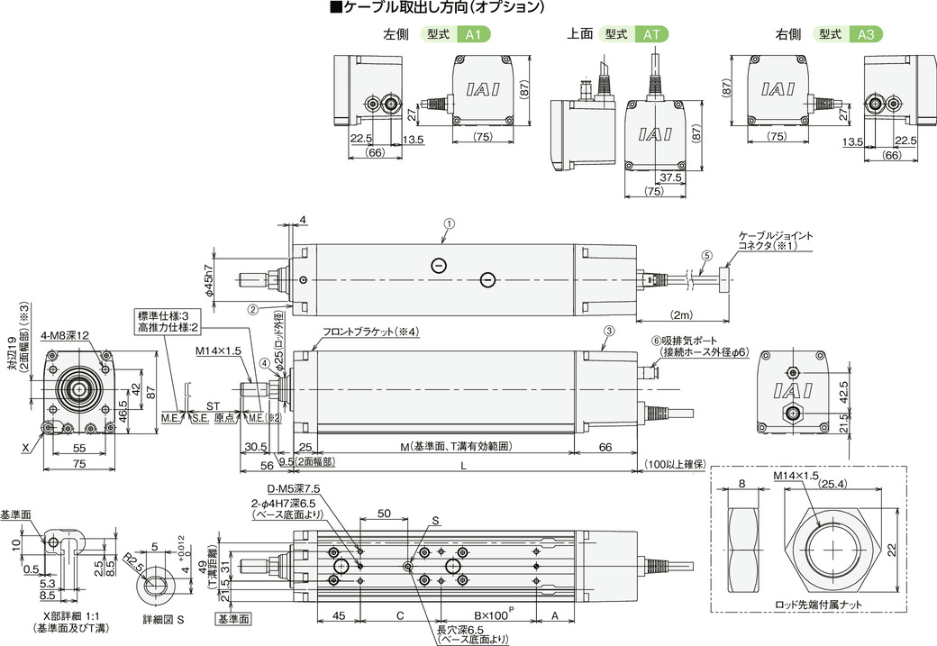
Dimensions
ST: Stroke
ME: Mechanical end
SE: Stroke end
*1 Connect the motor/encoder cable.
*2 When returning to the origin, the rod moves to the ME, so please be careful not to interfere with surrounding objects.
*3 The orientation of the width across flats varies depending on the product.
*4 When installing the main body using the front bracket and flange, make sure that no external force is applied to the main body.
Main Component Materials
| ① | Frame | Aluminum extrusion (equivalent to A6063SS-T5) White anodized |
| ② | Front bracket | Aluminum die casting |
| ③ | Rear cover | Aluminum die casting |
| ④ | rod | Stainless steel pipe (equivalent to SUS304) polished finish + hard chrome plating |
| ⑤ | Actuator Cable |
Polyvinyl chloride (PVC) |
| ⑥ | Intake and exhaust ports | Polyphenylene sulfide (PPS) |
Dimensions and weight by stroke
| stroke | 50 | 100 | 150 | 200 | 250 | 300 | 350 | 400 | 450 | 500 | ||
|---|---|---|---|---|---|---|---|---|---|---|---|---|
| L | No brakes | 361 | 411 | 461 | 511 | 561 | 611 | 661 | 711 | 761 | 811 | |
| With brake (Note 3) | 416 | 466 | 516 | 566 | 616 | 666 | 716 | 766 | 816 | 866 | ||
| A | No brakes | 40 | 40 | 40 | 40 | 40 | 40 | 40 | 40 | 40 | 40 | |
| With brake (Note 3) | 95 | 95 | 95 | 95 | 95 | 95 | 95 | 95 | 95 | 95 | ||
| B | 1 | 1 | 2 | 2 | 3 | 3 | 4 | 4 | 5 | 5 | ||
| C | 85 | 135 | 85 | 135 | 85 | 135 | 85 | 135 | 85 | 135 | ||
| D | 6 | 6 | 8 | 8 | 10 | 10 | 12 | 12 | 14 | 14 | ||
| M | No brakes | 270 | 320 | 370 | 420 | 470 | 520 | 570 | 620 | 670 | 720 | |
| With brake | 325 | 375 | 425 | 475 | 525 | 575 | 625 | 675 | 725 | 775 | ||
| Static allowable load at rod tip (N) | 112.7 | 91.5 | 76.7 | 65.7 | 57.2 | 50.4 | 44.8 | 40.2 | 36.2 | 32.7 | ||
| Rod tip dynamic allowable load (N) |
Load offset 0mm | 49.0 | 37.4 | 29.9 | 24.5 | 20.4 | 17.1 | 14.5 | 12.3 | 10.3 | 8.6 | |
| Load offset 100mm | 38.7 | 31.0 | 25.5 | 21.4 | 18.1 | 15.4 | 13.2 | 11.2 | 9.5 | 8.0 | ||
| Rod tip static allowable torque (N・m) | 11.4 | 9.3 | 7.9 | 6.8 | 6.0 | 5.4 | 4.9 | 4.5 | 4.1 | 3.8 | ||
| Rod tip dynamic allowable torque (N・m) | 3.9 | 3.1 | 2.5 | 2.1 | 1.8 | 1.5 | 1.3 | 1.1 | 1.0 | 0.8 | ||
| Mass (kg) |
No brakes | 5.7 | 6.2 | 6.7 | 7.3 | 7.8 | 8.3 | 8.8 | 9.3 | 9.8 | 10.3 | |
| With brake | 6.5 | 7.0 | 7.5 | 8.0 | 8.5 | 9.1 | 9.6 | 10.1 | 10.6 | 11.1 | ||
(Note 3) The price for the high thrust specification includes dimensions with brake.