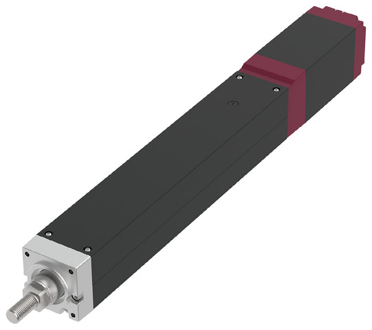
EC-RR8


*Note: Some pictures on this page are still Japanese version and the English version pictures are coming soon.
Main Specifications
| item | Contents | |||
|---|---|---|---|---|
| Lead | Ball screw lead (mm) | 10 | 5 | |
| Horizontal | Payload capacity | Maximum payload (kg) | 60 | 100 |
| Speed/Acceleration | Maximum speed (mm/s) | 300 | 150 | |
| Minimum speed (mm/s) | 13 | 7 | ||
| Rated acceleration/deceleration (G) | 0.2 | 0.1 | ||
| Maximum acceleration/deceleration (G) | 0.2 | 0.1 | ||
| vertical | Payload capacity | Maximum payload (kg) | 35 | 55 |
| Speed/Acceleration | Maximum speed (mm/s) | 240 | 150 | |
| Minimum speed (mm/s) | 13 | 7 | ||
| Rated acceleration/deceleration (G) | 0.2 | 0.1 | ||
| Maximum acceleration/deceleration (G) | 0.2 | 0.1 | ||
| Pressing | Maximum thrust when pressing (N) | 1000 | 2000 | |
| Maximum pressing speed (mm/s) | 10 | 10 | ||
| brake | Brake Specifications | Non-excitation electromagnetic brake | ||
| Brake holding force (kgf) | 35 | 55 | ||
| stroke | Minimum stroke (mm) | 50 | 50 | |
| Maximum stroke (mm) | 700 | 700 | ||
| Stroke pitch (mm) | 50 | 50 | ||
| item | Contents |
|---|---|
| Drive system | Ball screw φ16mm rolled C10 |
| Repeated positioning accuracy | ±0.02mm |
| Lost Motion | - (Cannot be indicated due to two-point positioning function.) |
| Linear guide | Direct-acting infinite circulation type |
| rod | φ40mm Material: Aluminum, hard anodized |
| Rod non-rotation accuracy (Note 6) | 0 degrees |
| Ambient temperature and humidity | 0 to 40°C, 85% RH or less (no condensation) |
| Protection Rating | IP20 |
| Vibration / Shock Resistance | 4.9m/s2 |
| Overseas Compliance Standards | CE Mark/RoHS Directive |
| Motor Type | Pulse Motor (□60) (Power Capacity: Max 6A) |
| Encoder Type | Incremental/Battery-less Absolute |
| Encoder Pulse Count | 800 pulse/rev |
| Deadline | Listed on the website under [Delivery Inquiry] |
(Note 6) This is the displacement angle of the rod's rotation direction under no load.
Payload table by speed/acceleration
The payload is in kg.
| posture | Horizontal |
|---|---|
| speed | Acceleration (G) |
| (mm/s) | 0.2 |
| 0 | 60 |
| 150 | 60 |
| 180 | 45 |
| 240 | 40 |
| 260 | 30 |
| 300 | 10 |
| Posture | Vertical |
|---|---|
| Speed | Acceleration (G) |
| (mm/s) | 0.2 |
| 0 | 35 |
| 88 | 35 |
| 100 | 30 |
| 110 | 28 |
| 120 | 23 |
| 130 | 18 |
| 140 | 15 |
| 150 | 11 |
| 160 | 10 |
| 170 | 8 |
| 180 | 7 |
| 190 | 5 |
| 200 | 4 |
| 220 | 3 |
| 240 | 2 |
| posture | Horizontal |
|---|---|
| Speed | Acceleration(G) |
| (mm/s) | 0.1 |
| 0 | 100 |
| 45 | 100 |
| 120 | 100 |
| 130 | 90 |
| 140 | 75 |
| 150 | 60 |
| posture | vertical |
|---|---|
| Speed | Acceleration(G) |
| (mm/s) | 0.1 |
| 0 | 55 |
| 35 | 55 |
| 60 | 50 |
| 70 | 35 |
| 90 | 20 |
| 100 | 15 |
| 120 | 10 |
| 150 | 2 |
Please use at speeds below.
・Lead 10: 260mm/s or less
・Lead 5: 140mm/s or less
Stroke and maximum speed
(Unit: mm/s)
| Lead (mm) |
50 to 350 (in 50mm increments) |
400 (mm) |
450 (mm) |
500 (mm) |
550 (mm) |
600 (mm) |
650 (mm) |
700 (mm) |
|---|---|---|---|---|---|---|---|---|
| 10 | 300<240> | 260<240> | 220 | 180 | 160 | 120 | 120 | 110 |
| 5 | 150 | 130 | 110 | 90 | 80 | 70 | 40 | 40 |
(Note) Values in < > are for vertical use.
Correlation diagram between pressing force and current limit value
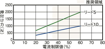
Precautions when performing pressing operation
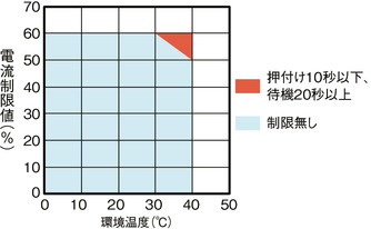
During high thrust pressing operations in high temperature environments,
Please use within the limits shown in the graph.
Adaptive Controller
(Note) The EC series has a built-in controller. For details on the built-in controller, see page
International Standards


Selection considerations
| (1) If the stroke is long, the maximum speed will decrease due to the dangerous rotation speed of the ball screw. Check the maximum speed of the desired stroke in "Stroke and Maximum Speed". (2) The maximum load capacity in "Main Specifications" is shown. For details, refer to "Table of Load Capacity by Speed and Acceleration". (3) The radial cylinder has a built-in guide. For details about the radial load acting on the rod, refer to page . (4) The horizontal load capacity is when used in conjunction with an external guide. (5) When performing a pressing operation, refer to "Correlation diagram between pressing force and current limit value". The pressing force is a guideline value. (6) Caution is required depending on the installation posture. For details, refer to page . (7) When connecting the RCON-EC connection specification (ACR) to the EC connection unit (RCON-EC-4), there is a limit to the number of units that can be connected. For details, refer to page |
Dimensions
ST: Stroke
ME: Mechanical end
SE: Stroke end
(Note) When performing a return to origin, the rod moves to the ME, so be careful not to let it interfere with the surroundings.
(Note) Pay attention to the length of the mounting bolts. When using mounting screws on the back of the base, if the bolts are long, they may interfere with the internal parts, causing abnormal sliding or damage to the parts.
(Note) The direction of the width across flats cannot be changed.
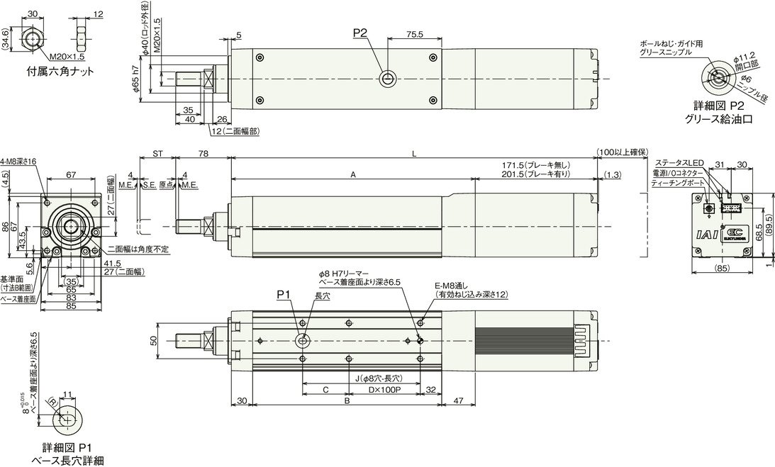
Stroke dimensions
| stroke | 50 | 100 | 150 | 200 | 250 | 300 | 350 | 400 | 450 | 500 | 550 | 600 | 650 | 700 | |
|---|---|---|---|---|---|---|---|---|---|---|---|---|---|---|---|
| L | No brakes | 463.5 | 513.5 | 563.5 | 613.5 | 663.5 | 713.5 | 763.5 | 813.5 | 863.5 | 913.5 | 963.5 | 1013.5 | 1063.5 | 1113.5 |
| With brake | 493.5 | 543.5 | 593.5 | 643.5 | 693.5 | 743.5 | 793.5 | 843.5 | 893.5 | 943.5 | 993.5 | 1043.5 | 1093.5 | 1143.5 | |
| A | 292 | 342 | 392 | 442 | 492 | 542 | 592 | 642 | 692 | 742 | 792 | 842 | 892 | 942 | |
| B | 215 | 265 | 315 | 365 | 415 | 465 | 515 | 565 | 615 | 665 | 715 | 765 | 815 | 865 | |
| C | 115 | 65 | 115 | 65 | 115 | 65 | 115 | 65 | 115 | 65 | 115 | 65 | 115 | 65 | |
| D | 0 | 1 | 1 | 2 | 2 | 3 | 3 | 4 | 4 | 5 | 5 | 6 | 6 | 7 | |
| E | 4 | 6 | 6 | 8 | 8 | 10 | 10 | 12 | 12 | 14 | 14 | 16 | 16 | 18 | |
| J | 115 | 165 | 215 | 265 | 315 | 365 | 415 | 465 | 515 | 565 | 615 | 665 | 715 | 765 | |
Mass by stroke
| stroke | 50 | 100 | 150 | 200 | 250 | 300 | 350 | 400 | 450 | 500 | 550 | 600 | 650 | 700 | |
|---|---|---|---|---|---|---|---|---|---|---|---|---|---|---|---|
| Mass (kg) |
No brakes | 6.7 | 7.2 | 7.6 | 8.1 | 8.6 | 9.1 | 9.6 | 10.1 | 10.5 | 11.0 | 11.5 | 12.0 | 12.5 | 13.0 |
| With brake | 7.3 | 7.8 | 8.2 | 8.7 | 9.2 | 9.7 | 10.2 | 10.7 | 11.1 | 11.6 | 12.1 | 12.6 | 13.1 | 13.6 | |
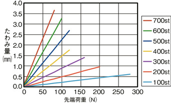
Rod deflection amount (reference value)