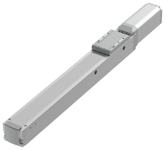
RCS4-HSA6C


*Note: Some pictures on this page are still Japanese version and the English version pictures are coming soon.
Main Specifications
| item | Contents | |||||
|---|---|---|---|---|---|---|
| Lead | Ball screw lead (mm) | 24 | 16 | 8 | 4 | |
| Horizontal | Payload capacity | Maximum payload (kg) (Note 3) | 18 | 33 | 50 | 90 |
| Speed/Acceleration | Maximum speed (mm/s) | 1500 | 1000 | 500 | 240 | |
| Rated acceleration/deceleration (G) | 0.3 | 0.3 | 0.3 | 0.3 | ||
| Maximum acceleration/deceleration (G) | 1.2 | 1.2 | 1 | 0.7 | ||
| vertical | Payload capacity | Maximum payload (kg) (Note 3) | 4 | 6 | 15 | 30 |
| Speed/Acceleration | Maximum speed (mm/s) | 1500 | 1000 | 500 | 240 | |
| Rated acceleration/deceleration (G) | 0.3 | 0.3 | 0.3 | 0.3 | ||
| Maximum acceleration/deceleration (G) | 1.2 | 1.2 | 1 | 0.7 | ||
| Thrust | Rated thrust (N) | 71 | 106 | 212 | 425 | |
| brake | Brake Specifications | Non-excitation electromagnetic brake | ||||
| Brake holding force (kgf) | 4 | 6 | 15 | 30 | ||
| stroke | Minimum stroke (mm) | 50 | 50 | 50 | 50 | |
| Maximum stroke (mm) | 800 | 800 | 800 | 800 | ||
| Stroke pitch (mm) | 50 | 50 | 50 | 50 | ||
(Note 3) When the double slider specification (W) is selected, the maximum payload capacity decreases. See the table below for details.
(Note) When the double slider specification (W) is selected, Lead 24 cannot be selected.
| item | Contents |
|---|---|
| Drive system | Ball screw φ12mm rolled C10 |
| Repeated positioning accuracy (Note 4) | ±0.01mm 【±0.005mm】 |
| Lost Motion | Less than 0.1 mm |
| base | Material: Aluminum, white anodized |
| Linear guide | Direct-acting infinite circulation type |
| Static allowable moment (Note 5) |
Ma: 65 N・m [546 N・m] |
| Mb: 75 N・m [779 N・m] | |
| Mc: 120 N・m [205 N・m] | |
| Dynamic allowable moment (Note 5) (Note 6) |
Ma: 33.7 N・m [167 N・m] |
| Mb: 40.2 N・m [199 N・m] | |
| Mc: 55.3 N・m [89.8 N・m] | |
| Ambient temperature and humidity | 0 to 40°C, 85% RH or less (no condensation) |
| Protection rating | IP20 |
| Vibration and shock resistance | 4.9m/ s2 |
| Overseas compatible standards | CE mark, RoHS directive |
| Motor Type | AC servo motor |
| Encoder Type | Battery-less absolute |
| Encoder Pulse Number | 16384 pulses/rev |
| deadline | Listed on the website [Delivery Date Inquiry] |
(Note 4) Values in brackets [ ] are for high precision specifications (leads 4, 8, 16).
(Note 5) Values in brackets [ ] are for when the double slider specification (W) is selected.
(Note 6) Based on a standard rated life of 5,000 km. The running life will vary depending on the operating conditions and installation. Please check the running life on page
Slider type moment direction
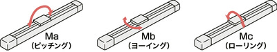
Table of payload capacity by acceleration
The unit of payload is kg. Blank spaces mean the item cannot be operated.
| posture | Horizontal | vertical | |||||||||
|---|---|---|---|---|---|---|---|---|---|---|---|
| Lead (mm) |
Maximum speed (mm/s) |
Acceleration (G) | |||||||||
| 0.3 | 0.5 | 0.7 | 1.0 | 1.2 | 0.3 | 0.5 | 0.7 | 1.0 | 1.2 | ||
| 24 | 1500 | 18 | 15 | 10 | 8.0 | 6.0 | 4 | 4 | 4 | 4 | 2 |
| 16 | 1000 | 33 | 24 | 20 | 15 | 13 | 6 | 6 | 6 | 6 | 6 |
| 8 | 500 | 50 | 40 | 30 | 20 | 15 | 15 | 15 | 15 | ||
| 4 | 240 | 90 | 60 | 40 | 30 | 25 | 20 | ||||
Stroke and maximum speed
(Unit: mm/s)
| stroke Lead |
50 to 500 (in 50mm increments) |
550 (mm) |
600 (mm) |
650 (mm) |
700 (mm) |
750 (mm) |
800 (mm) |
|---|---|---|---|---|---|---|---|
| 24 | 1500 | 1440 | 1240 | 1095 | 965 | 850 | 760 |
| 16 | 1000 | 965 | 830 | 720 | 635 | 560 | 500 |
| 8 | 500 | 475 | 410 | 355 | 315 | 275 | 245 |
| 4 | 240 | 235 | 205 | 175 | 155 | 135 | 120 |
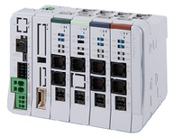
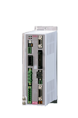
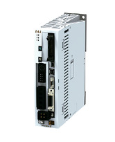
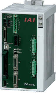
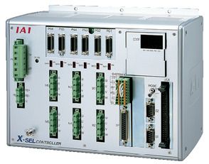
Adaptive Controller
The actuators on this page can be operated with the following controllers. Please select the type that suits your application.
| name | exterior | Maximum number of connectable axes |
Power supply voltage | Control Method | Maximum number of positioning points | ||||||||||||||
|---|---|---|---|---|---|---|---|---|---|---|---|---|---|---|---|---|---|---|---|
| Positioner | Pulse train | program | Network ※Select | ||||||||||||||||
| DV | CC | CIE | PR | CN | ML | ML3 | EC | EP | PRT | SSN | ECM | ||||||||
 |
16 (ML3, SSN, ECM are 8) |
DC24V Single-phase AC200V Three-phase AC200V |
- | - | - | ● | ● | ● | ● | - | - | ● | ● | ● | ● | ● | ● | 128 (ML3, SSN, ECM no position data) |
|
 |
8 | - | - | ● | ● | ● | ● | ● | - | - | - | ● | ● | ● | - | - | 36000 | ||
 |
1 | Single phase AC 100V/200V |
● | ● | - | ● | ● | ● | ● | ● | ● | ● | ● | ● | ● | - | ● | 512 (network specification is 768) |
|
 |
1 | Single phase AC100V | ● | ● | - | ● | ● | ● | - | - | - | ● | ● | ● | ● | - | - | 384 | |
 |
1 | Single phase AC200V | ● | ● | - | ● | ● | ● | - | - | - | ● | ● | ● | ● | - | - | 384 | |
 |
6 | Single-phase AC200V Three-phase AC200V |
- | - | ● | ● | ● | - | ● | - | - | - | - | ● | - | - | - | 20000 | |
 |
8 | - | - | ● | ● | ● | ● | ● | - | - | - | ● | ● | - | - | - | 55000 (varies by type) |
||
(Note) For network abbreviations such as DV and CC, please see page
(Note) For ML3 and EC of SCON2, if there is no function option of the controller model, the remote I/O specification will be used. If "M" is selected as the function option, the motion network specification will be used.
International Standards


Selection considerations
| (1) As the stroke becomes longer, the maximum speed decreases due to the critical rotation speed of the ball screw. Check the maximum speed for the desired stroke in "Stroke and maximum speed". (2) As the acceleration increases, the payload decreases. For details, refer to the "Payload capacity by acceleration" table. (3) The usable duty ratio varies depending on the operating conditions (payload, acceleration/deceleration, etc.). For details, refer to page . (4) Caution is required depending on the mounting position. For details, refer to page . (5) The guideline for the overhang load length is 300 mm or less in the Ma, Mb, and Mc directions (600 mm or less for double slider specifications). For details on the overhang load length, refer to the explanation on page . (6) For the order type and precautions for double slider specifications, refer to page |
Dimensions
ST: Stroke
ME: Mechanical end
SE: Stroke end
(Note) Connect the motor cable and encoder cable to the cable joint connector.
For cables, see page
(Note) When performing origin return, the slider moves to the ME, so be careful not to let it interfere with surrounding objects.
(Note) Please note that return adjustment is required to change the origin direction.
English version is coming soon!
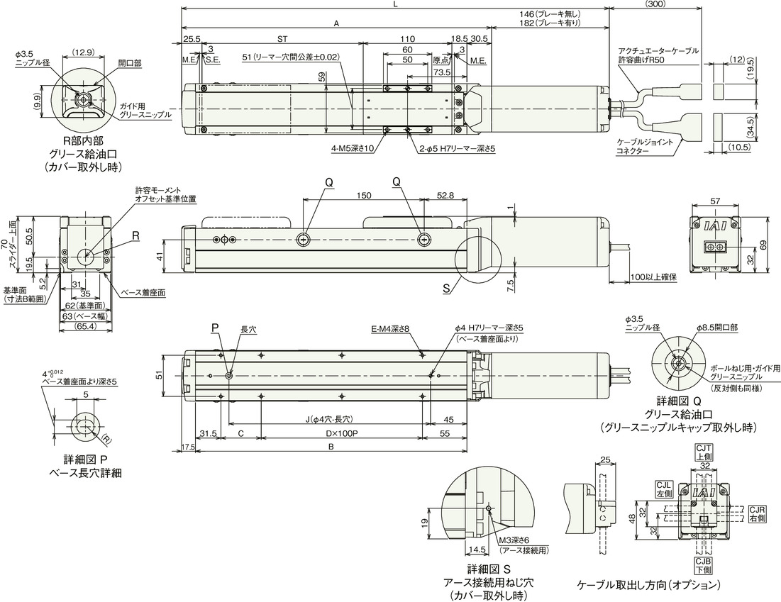
Stroke dimensions
| stroke | 50 | 100 | 150 | 200 | 250 | 300 | 350 | 400 | 450 | 500 | 550 | 600 | 650 | 700 | 750 | 800 | |
|---|---|---|---|---|---|---|---|---|---|---|---|---|---|---|---|---|---|
| L | No brakes | 380.5 | 430.5 | 480.5 | 530.5 | 580.5 | 630.5 | 680.5 | 730.5 | 780.5 | 830.5 | 880.5 | 930.5 | 980.5 | 1030.5 | 1080.5 | 1130.5 |
| With brake | 416.5 | 466.5 | 516.5 | 566.5 | 616.5 | 666.5 | 716.5 | 766.5 | 816.5 | 866.5 | 916.5 | 966.5 | 1016.5 | 1066.5 | 1116.5 | 1166.5 | |
| A | 234.5 | 284.5 | 334.5 | 384.5 | 434.5 | 484.5 | 534.5 | 584.5 | 634.5 | 684.5 | 734.5 | 784.5 | 834.5 | 884.5 | 934.5 | 984.5 | |
| B | 186.5 | 236.5 | 286.5 | 336.5 | 386.5 | 436.5 | 486.5 | 536.5 | 586.5 | 636.5 | 686.5 | 736.5 | 786.5 | 836.5 | 886.5 | 936.5 | |
| C | 0 | 50 | 0 | 50 | 0 | 50 | 0 | 50 | 0 | 50 | 0 | 50 | 0 | 50 | 0 | 50 | |
| D | 1 | 1 | 2 | 2 | 3 | 3 | 4 | 4 | 5 | 5 | 6 | 6 | 7 | 7 | 8 | 8 | |
| E | 4 | 6 | 6 | 8 | 8 | 10 | 10 | 12 | 12 | 14 | 14 | 16 | 16 | 18 | 18 | 20 | |
| J | 100 | 150 | 200 | 250 | 300 | 350 | 400 | 450 | 500 | 550 | 600 | 650 | 700 | 750 | 800 | 850 | |
Mass by stroke
| stroke | 50 | 100 | 150 | 200 | 250 | 300 | 350 | 400 | 450 | 500 | 550 | 600 | 650 | 700 | 750 | 800 | |
|---|---|---|---|---|---|---|---|---|---|---|---|---|---|---|---|---|---|
| Mass (kg) |
No brakes | 1.8 | 2.1 | 2.4 | 2.7 | 3 | 3.3 | 3.6 | 3.9 | 4.2 | 4.5 | 4.8 | 5.1 | 5.4 | 5.7 | 6 | 6.3 |
| With brake | 2.1 | 2.4 | 2.7 | 3 | 3.3 | 3.6 | 3.9 | 4.2 | 4.5 | 4.8 | 5.1 | 5.4 | 5.7 | 6 | 6.3 | 6.6 | |
Load capacity by acceleration (double slider type)
The unit of payload is kg. Blank spaces mean the item cannot be operated.
| posture | Horizontal | vertical | ||||||||
|---|---|---|---|---|---|---|---|---|---|---|
| Lead (mm) |
Maximum speed (mm/s) |
Acceleration (G) | ||||||||
| 0.3 | 0.5 | 0.7 | 1.0 | 1.2 | 0.3 | 0.5 | 0.7 | 1.0 | ||
| 16 | 1000 | 27 | 18 | 14 | 9 | 7 | ||||
| 8 | 500 | 44 | 34 | 24 | 14 | 9 | 9 | 9 | 9 | |
| 4 | 240 | 84 | 54 | 34 | 24 | 19 | 14 | |||
Dimensions (double slider type)
ST: Stroke
ME: Mechanical end
SE: Stroke end
Drawing (double slider specification)
(Note) Connect the motor cable and encoder cable to the cable joint connector.
For cables, see page
(Note) When performing origin return, the slider moves to the ME, so be careful not to let it interfere with surrounding objects.
(Note) Please note that return adjustment is required to change the origin direction.
English version is coming soon!
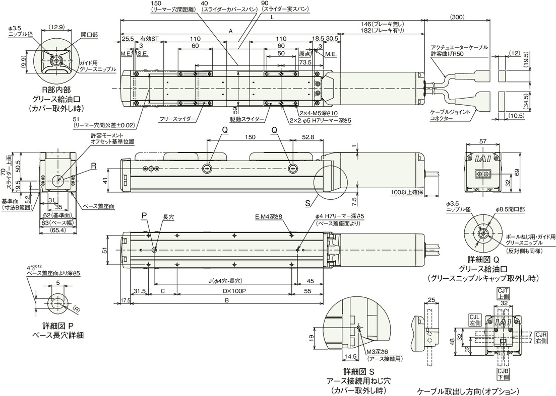
Stroke dimensions
| Nominal stroke | 200 | 250 | 300 | 350 | 400 | 450 | 500 | 550 | 600 | 650 | 700 | 750 | 800 | |
|---|---|---|---|---|---|---|---|---|---|---|---|---|---|---|
| Effective Stroke | 50 | 100 | 150 | 200 | 250 | 300 | 350 | 400 | 450 | 500 | 550 | 600 | 650 | |
| L | No brakes | 530.5 | 580.5 | 630.5 | 680.5 | 730.5 | 780.5 | 830.5 | 880.5 | 930.5 | 980.5 | 1030.5 | 1080.5 | 1130.5 |
| With brake | 566.5 | 616.5 | 666.5 | 716.5 | 766.5 | 816.5 | 866.5 | 916.5 | 966.5 | 1016.5 | 1066.5 | 1116.5 | 1166.5 | |
| A | 384.5 | 434.5 | 484.5 | 534.5 | 584.5 | 634.5 | 684.5 | 734.5 | 784.5 | 834.5 | 884.5 | 934.5 | 984.5 | |
| B | 336.5 | 386.5 | 436.5 | 486.5 | 536.5 | 586.5 | 636.5 | 686.5 | 736.5 | 786.5 | 836.5 | 886.5 | 936.5 | |
| C | 50 | 0 | 50 | 0 | 50 | 0 | 50 | 0 | 50 | 0 | 50 | 0 | 50 | |
| D | 2 | 3 | 3 | 4 | 4 | 5 | 5 | 6 | 6 | 7 | 7 | 8 | 8 | |
| E | 8 | 8 | 10 | 10 | 12 | 12 | 14 | 14 | 16 | 16 | 18 | 18 | 20 | |
| J | 250 | 300 | 350 | 400 | 450 | 500 | 550 | 600 | 650 | 700 | 750 | 800 | 850 | |
(Note) Nominal stroke: Model stroke Effective stroke: Actual operating stroke
Mass by stroke
| Nominal stroke | 200 | 250 | 300 | 350 | 400 | 450 | 500 | 550 | 600 | 650 | 700 | 750 | 800 | |
|---|---|---|---|---|---|---|---|---|---|---|---|---|---|---|
| Effective Stroke | 50 | 100 | 150 | 200 | 250 | 300 | 350 | 400 | 450 | 500 | 550 | 600 | 650 | |
| Mass (kg) |
No brakes | 3.26 | 3.56 | 3.86 | 4.16 | 4.46 | 4.76 | 5.06 | 5.36 | 5.66 | 5.96 | 6.26 | 6.56 | 6.86 |
| With brake | 3.56 | 3.86 | 4.16 | 4.46 | 4.76 | 5.06 | 5.36 | 5.66 | 5.96 | 6.26 | 6.56 | 6.86 | 7.16 | |
(Note) Mass is the sum of the single slider specification and the free slider (0.56 kg).