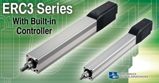
space-saving ERC3 ROBO Cylinder®.

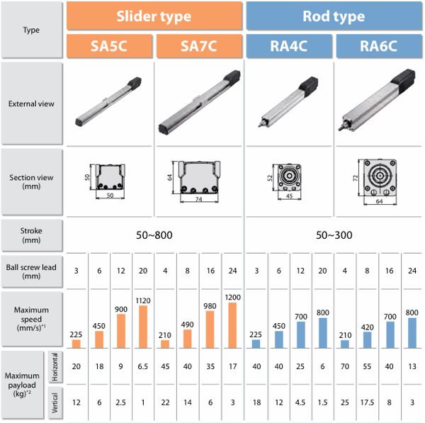
(Notes) All of the values shown above assume that the high-output setting is enabled.
*1. The maximum speed may not be reached when the stroke is shorter. Also note that the longer the stroke, the lower the maximum speed becomes in order to avoid reaching a dangerous speed. For details, refer to the specification page of each model.
*2. The maximum payload is based on operation at the rated acceleration. The higher the acceleration, the lower the maximum payload becomes. For details, refer to the table of payloads by acceleration on p.26.
Great Features Made Possible by the Built-in Controller

No space is required for installing the controller, so the control panel can be made smaller.
A smaller control panel allows for effective use of space.


Built-in Controller Offers Excellent Scalability

1. "Conventional" Method
The ERC3 series can be connected to a PLC or other host device in the manner illustrated below. Up to 16 positioning points are supported.
- The ERC3 series can be controlled directly via PIOs from the PLC, etc., just like the conventional ERC2 series.
- The ERC3 series can be controlled directly via SIOs from the PLC, etc., just like the conventional ERC2 series.
- The ERC3 series can be pulse-train controlled in the line-driver mode.

2. "PIO converter" Method
Various functions offered by the ERC3’s built-in controller can be enhanced by connecting the PIO converter.
- All six PIO patterns will be supported and the maximum number of positioning points will increase to 512.
- The ERC3’s encoder can be operated in the simple absolute mode.
- The drive source can be cut off using the built-in relay (CV) or external relay (CVG).
- Calendar function can be used.
- Equipped with a brake release switch for the ERC3.
- Various statuses of the ERC3 can be checked in a simple mode.

3. Quick Teach Method
When the Quick Teach is connected, test runs can be performed without supplying power to the ERC3.

- Power can be supplied from the Quick Teach.
- Speed, acceleration and position can be changed.
- Power supply specifications of 24 VDC and 100/200 VAC are supported.*
* The ERC3 series may not operate as specified if test runs are performed using the Quick Teach connected to a power-supply unit, with the high power output setting is enabled. (Position data can be edited without problems.)
If you want to perform test runs with the high-output setting enabled, connect a 24-VDC power supply to the Quick Teach and disconnect the power-supply unit.

Features of the PIO Converter
Realizing higher-class controller functions with the ERC3 series
When connected to the PIO converter, the ERC3 series can demonstrate functions equivalent to the RCP4 controller "PCON-CA." Use the PIO converter if you want to configure a high-function system using the ERC3 series, use the absolute function or monitor the status of the actuator.

 While the maximum number of positioning points supported by the ERC3 series’ built-in controller is 16, it increases to 512 when the PIO converter is connected. Connecting the PIO converter also increases the numbers of I/O signals, allowing for complex controls and connection with peripheral equipment.

 The standard encoder of the ERC3 series is of the incremental type. Once the power is turned off, therefore, the actuator’s current position is lost and the home return operation will be required next time the actuator is started. When the PIO converter is connected, the ERC3 lets you select the simple absolute mode. Home return operation is not required while the encoder is in the simple absolute mode, because the current position is in memory.

 The PIO converter lets you check the following statuses using the status LEDs provided on the front panel (optional).
- Command current ratio
- Alarm code
- PIO input terminal status
- PIO output terminal status

 The PIO converter has a calendar function that lets you check the details of past alarms, such as when each alarm occurred, by connecting the teaching pendant and PC software to the PIO converter. This function is useful when analyzing alarms.

 If your ERC3 actuator comes with a brake, the brake can be turned on/off freely using the brake release switch on the front panel of the PIO converter. To release the brake, turn the switch to the "RLS" position.
Features of the Quick Teach
The ERC3 can be operated right away.
 The Quick Teach lets you operate the actuator with ease using the buttons and knobs on the operation panel, without having to supply power or sending signals from a PLC. By using the Quick Teach, you can change the number of stop positions (2 points or 3 points) and each stop position, speed, and acceleration, and perform test run (forward/back movement and continuous operation).
Changing the acceleration/speed

- Press and hold the MANUAL button.
- Press the HOME button.
- Confirm that the Accel & Speed LED is lit.
- Press the button corresponding to the stop position (FWD POS / MIDDLE POS / BACK POS) where you want to change the acceleration/speed. (* The MIDDLE POS button is available when the actuator is stopping at three points.)
- Turn the Accel/Speed knobs. (* You can use the knobs to change the acceleration and speed within a range of 1% to 100% of the rated acceleration/deceleration and maximum speed, respectively. The minimum speed may not be 1% of the maximum speed, depending on the actuator. Refer to the operation manual for the minimum speed.)
- Press the SAVE button.
Changing the position

- Press and hold the MANUAL button.
- Press the HOME button.
- Press the STOP POS NUM button and determine the number of stop positions.
- Press the TEACH MODE. (Both the Accel & Speed LED and Position LED should illuminate.)
- Press the button corresponding to the stop position (FWD POS / MIDDLE POS / BACK POS) where you want to change the position. (* The MIDDLE POS button is available when the actuator is stopping at three points.)
- Move the actuator to a desired position. (* You can jog the actuator or turn off the servo and move the actuator by hand.)
- Press the SAVE button. (* Exercise caution because the conditions of the Accel/Speed knobs will also be saved together with the position.)
Performing test run (continuous operation)

- Press and hold the MANUAL button.
- Press the HOME button.
- Press the RUN button. (* The actuator will move back and forth between the "forward position and back position" if it has been set to stop at two points. The actuator will move repeatedly in the sequence of "forward position ➞ middle position ➞ back position ➞ forward position" if it has been set to stop at three points.)
- Press the STOP button to stop the operation.
Application Examples
 This system prints on components using an inkjet printer. The ERC3 is used to move components. Since the ERC3 can operate at a constant speed, stable printing quality can be achieved. This system prints on components using an inkjet printer. The ERC3 is used to move components. Since the ERC3 can operate at a constant speed, stable printing quality can be achieved. |
 Comprising of the ERC3 and the Quick Teach, this system is used to agitate a liquid such as a chemical agent. Use of the Quick Teach makes it possible to operate the system without a PLC and set the oscillation band and speed to the desired levels. Comprising of the ERC3 and the Quick Teach, this system is used to agitate a liquid such as a chemical agent. Use of the Quick Teach makes it possible to operate the system without a PLC and set the oscillation band and speed to the desired levels. |
 This ERC3-based system palletizes automobile components. Two axes are arranged separately to pick components and place them onto the pallet. The takt time can be reduced by performing approach and return at high speed and placement at low speed. This ERC3-based system palletizes automobile components. Two axes are arranged separately to pick components and place them onto the pallet. The takt time can be reduced by performing approach and return at high speed and placement at low speed. |
 This ERC3-based system conducts life test on electronic equipment. The push speed and force can be changed according to the product. This ERC3-based system conducts life test on electronic equipment. The push speed and force can be changed according to the product. |


